Installation
The phono cartridge should be located
as
far
as
is convenient from any transformers, motors, or
other source of AC magnetic field. With proper
installation and a good cartridge, no AC hum
should be audible even at the full setting of the
volume control and with bass boost.
B.
USE
OF PHONOG RAPH PICKUPS OTHER
THAN SHURE V15 TYPE II
The phonograph pre-amplifiers
as
shipped
are
optimized for the Shure V15 Type II pickup.
Other good quality pickups can be used, but a
resistor change on each of the phono pre-amp
boards may be required. The resistors in question
are
designated R1 as shown near the left side of
the pre-amp schematic in Section VI, A. To
determine the optimum value for R1 for a given
pickup, the inductance and resistance of the pick
up must be known. The value for resistor R1 may
then be calculated by using the following equation:
L
I
R
x 106 - 100 Ro - 20K
1
.75
Where
Lo is pickup inductance in Henries, Ro is
pickup
internal resistance in ohms, and R 1 is in
ohms.
Once the value for R1 has been calculated
R1 resistors on each of the two phono pre-am
p
boards
should be changed to the proper value. For
additional information, see Section V, A.
LEFT SPEAKER
The Barney Oliver Audio Amplifier
C.
SPEAKER CONNECTIOI\lS
The amplifier may be located at any con
venient distance from the loudspeakers. Twisted
pairs of No. 18 wire or larger or ordinary zip-cord
may be used to connect the amplifiers to the
speakers if the distance is under 100 feet. For
longer distances, heavier conductors are recom
mended. In general the d-c resistance of the
cables or cords should not exceed 5% of the
speaker impedance.
Connection to the amplifier outputs is via
the two-terminal polarized Jones sockets at the
rear of the amplifier. The cords or cables must be
soldered to the mating plugs provided, taking care
to avoid internal short circuits from wire strands
or solder bridges. It is good practice to insulate
the wire and lugs from each other with electrical
tape or heat shrinkable tubing inside the plug
sleeve after soldering.
D.
SPEAKER PLACEMENT
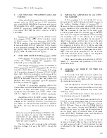
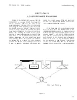
The loudspeakers should be located at the
ends of the base of an isosceles triangle with the
listener at the apex. The apex angle of this tri
angle, i.e., the angle between the lines of sight
to the two speakers should be about 150 to 450
as shown in Figure 2. Good sound quality wil
l
then be heard up to 450 on either side of the
perpendicular bisector of the line between the
speakers.
RIGHT SPEAKER
\
3-2
\
BISECTOR
\
\
\
\
\
\
\
, ' .
\
Figure 2.
Содержание Barney Oliver
Страница 1: ... 3 AMPLIfIER ...
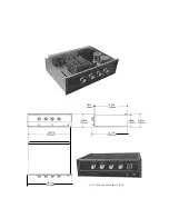
Страница 11: ... ____ 10 93in 278 NOTE CASE IS AN EXTRA PRICE OPTION ...
Страница 16: ...eTION V I IR UIT DIAGRAMS ...


