The Barney Oliver Audio
Circuit
5
TI N V
IR
UIT D
CRt TIONS
A.
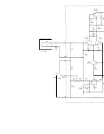
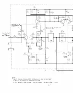
PHONO-P RE-AM P LIFIER
The phono pre-amplifier uses a combina
tion of series and shunt feedback to the
terminals to
a resistive input
of the proper value to produce,
self inductance of the
the
with the
RIA A
roll-off above 2120 Hz. If
is
and
inductance and Ro the
is the input resistance to the pre-amp we
require that
'" 7 5 x 10⁻⁶ seconds
This leads to the value of Rl
in the sche-
matic. As
Rl is
for the
Shure V-15
To provide the .16 dB
variation of high end response, the shunt feed
back is halved or doubled.
The series feedback is applied to the low end
of the
which places these ends
(normally the outer shields of coaxial .
�O?
above
To avoid hum and RF pIckup It
IS
recommended that an outer shield insulated
both
inner shields be used. This shield should
connect the record
frame to the
chassis.
A balanced differential
is used at the
input to avoid drift and RF rectification. The
remainder of the
is similar to the power
for power leveL The
Class
B stage can supply a 600!J line or headphones
at line level (0
without
distortion.
The low end bass boost of the RIAA charac
teristic below 500 Hz is provided by C12 and R3
+
R4
+
R5
+
R6 and R28. The low end cutoff is
provided
C2 and C3
with C4, C5 and
RIO. This combination
doc external
and a fourth order maximally flat low-end
cutoff at about 16 to 20 Hz.
was used to make the projected
circuit zero in all directions
the conductors and by
shown. This minimizes the
to the power transformer and reduces
the hum below audibility.
you notice any
hum, it's from
directly to the cartridge.)
Because the
10 K !J
)
cable
impedance is low (about
has no effect on the
up to 10 or 20 feet
high end response for
on the cable used.
Many of the components that may
you, such as Q3 or CR8 or such as CRl,
are there to avoid tum on transients or
avoid emitter base breakdown. Everything has a
function, but invincible fatigue prevents me from
going into all the gory details.
B.
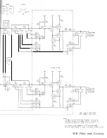
FI LTER BOARD
The filter board
a sharp low-end
cutoff below 16 Hz to
the speakers
large useless cone exursions, and a control
lable high-end cutoff to suppress the
fre-
with
or distorted program material.
The board contains four
gain
of two cascaded emitter followers
and
with constant current supplies
and Q7). This combination provides
very high
very low output im-
and low distortion.
The two
are
to the
selector switch through active
high pass filters that
rapidly in transmission
below 16 Hz (example:
C3,
Q5).
The output of these feed the mode selector switch.
The
unity
amplifiers provide
drive for the dual precision volume control and
are coupled to the mode selector switch via active
low-pass filters.
are three
filters, two
of the
by the input RC net-
poles
zeros) by the
are provided to supply the
base currents of the input emitter
and
thereby enable the
at terminals 5,
20
and 21 to be set equal to zero. This eliminates
transients when the mode and filter switches are
switched.
5-1
Содержание Barney Oliver
Страница 1: ... 3 AMPLIfIER ...
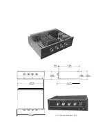
Страница 11: ... ____ 10 93in 278 NOTE CASE IS AN EXTRA PRICE OPTION ...
Страница 16: ...eTION V I IR UIT DIAGRAMS ...


