


The
Oliver Audio
Installation
TION III
INS TA
A.
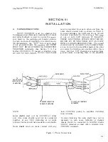
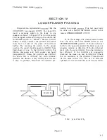
PHONO CONNECTIONS
must be observed for
the
input. Because a combination of shunt
and series feedback is used to control the
ance faced
the
and thereby
the high end roll-off
by the RIAA record-
characteristic, the
side of each input
is not grounded inside the
and THESE
MUST
NOT
BE GROUNDED
CONNECTED
TOGETHER
(See Section V, A. for
further
coaxial or shielded wires
the two inner shields
LATION
must be insulated from each other and from the
outer shield around both as shown in
l.
In some cartridges, the LOW side of one or both
channels is grounded to the case
a thin
at one or both LOW terminals.
THESE GROUNDING STRAPS MUST BE RE
MOVED BY PRYING THEM OUT AND OFF
WITH A LARGE NEEDLE OR PICK. The overall
shield should be connected to the turntable frame
at one end and to the amplifier chassis at the other
end
the
post provided. After this is
done, test that
channels are isolated from
ground before connecting them to the amplifier.
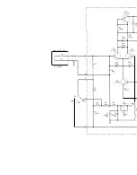
PHON
6
01N
pur
JACKS ON REAR
l
OF AMPLIfiER
OUTER SHIELD
NOTE:
TO
GROUND CONNECTION
ON REAR Of AMPLIfiER
Inner shields
must
not
be
at either
end. Also inner shields must not be connected
together at any
(including at or inside
pickup). Cables should have insulation over shields.
Outer"
shield
must not make contact with any
lead
TO CHASSIS Of TURNTABLE
OR CHANCER
pickup to amplifier
inner shields).
In some locations the outer shield may not be
necessary; in such cases, turntable or changer
chassis should be connected to
chassis
terminal on rear) with a
WIre,
insulated.
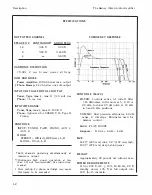
Figure 1. Phono Connections
3-1
Содержание Barney Oliver
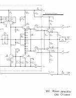
Страница 1: ... 3 AMPLIfIER ...
Страница 11: ... ____ 10 93in 278 NOTE CASE IS AN EXTRA PRICE OPTION ...
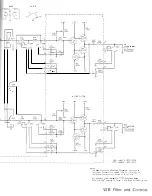
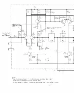
Страница 16: ...eTION V I IR UIT DIAGRAMS ...


