


29
Installing and removing a VPM module
The VPM module performs voice traffic compression/decompression, EC, and CNG.
The following VPM module types are available:
8-channel VPM (RT-VPM8)
16-channel VPM (RT-VPM16)
24-channel VPM (RT-VPM24)
32-channel VPM (RT-VPM32)
Figure 30
VPM module
Installing a VPM module
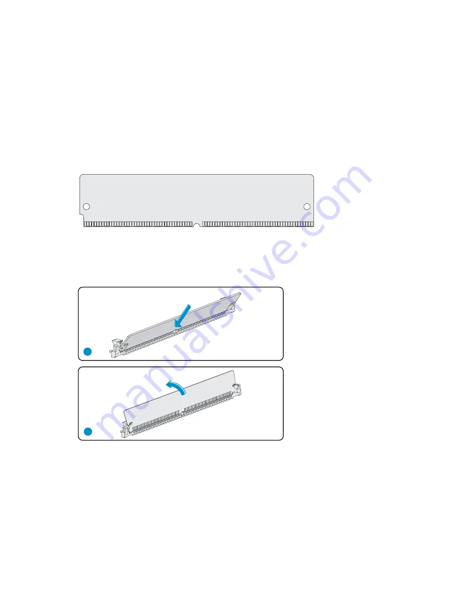
Figure 31
Installing a VPM module
2
1
To install a VPM module, as shown in
Figure 31
:
1.
Align the golden finger of the VPM module with the VPM module slot on the router’s motherboard.
Insert the VPM module into the slot at a 45-degree angle.
2.
Tilt the VPM module up to the vertical position until you hear a click, which indicates that the VPM
module is seated properly in the slot.


