

BS-GS2008P/BS-GS2016P/BS-GS2024P
Business switch ................................................................................ 1
Power cable....................................................................................... 1
AC adapter (BS-GS2008P only)................................................... 1
19 inch rack metal fittings
(BS-GS2016P, BS-GS2024P only).............................................. 2
19 inch rack metal fittings screws
(BS-GS2016P, BS-GS2024P only).............................................. 8
- Keep the warranty statement at hand to request covered repairs.
- Unless clearly permitted in the product documentation, do not use
other accessories (such as cables) with this product other than
those included in the package.
Screws for 19 inch rack
(BS-GS2016P, BS-GS2024P only).............................................. 4
Power cable retaining band ........................................................ 1
Rubber feet........................................................................................ 4
Serial number label......................................................................... 1
Warranty statement........................................................................ 1
Package Contents
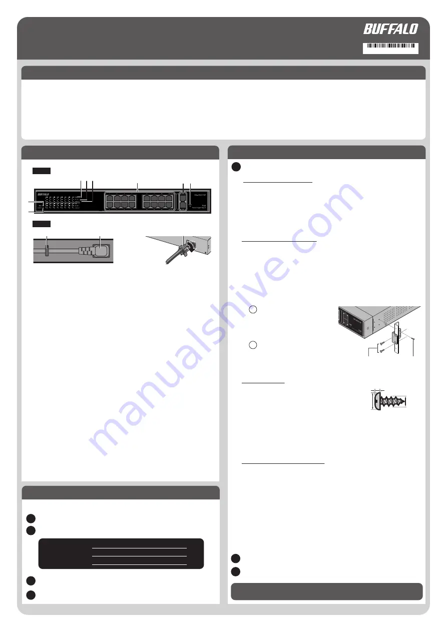
Diagrams and Layout
1. Diag LED
On (green): The switch is in normal condition.
On (red): Booting, executing self-diagnostic, or initializing.
Blinking (red): A fan error occurred. (BS-GS2016P/2024P only)
Slow blinking (red): A loop is detected.
7. SFP Ports
(BS-GS2016P,
BS-GS2024P only)
Front
Quick Setup Guide
On (green): Power is on.
Off: Power is off.
2. Power LED
On (green): 1000 Mbps link.
On (amber): 100 Mbps link.
Off: 10 Mbps link or no link.
4. Speed LEDs
5. Link/Act LEDs
On: Link is established.
Blinking: Transmitting data.
Off: Link is not established.
6. PoE Ports
These Ethernet ports support PoE. Connect devices that need
Ethernet power to these ports.
Connect your SFP modules to these ports.
8. Reset Button
Press and holdthis button for 3 seconds to initialize the switch.
The figure below is an example of BS-GS2016P.
2. Installation
Floor or Shelf Mounting
Attach the supplied rubber feet to the bottom corners of the unit before use.
Notes:
- Place the switch on a flat surface near the AC inlet. Set it more than 2 inches from
the wall for aeration.
- To use multiple switches in a stack, attach the rubber feet to each switch and
stack them on top of each other.
Install metal fittings on the switch
by using screws for 19 inch rack.
Remove rubber feet if attached.
Use 4 metal fittings screws to fix the
switch on the rack.
Wall Mounting
To mount the unit to a wall, use 2 screws (not
included) with the dimensions shown on the right.
Screws should be installed with distance apart as
below. Slide the mounting holes on the base of the
switch over them.
BS-GS2008P: 3.34 inches
BS-GS2016P: 7.01 inches
BS-GS2024P: 11.07 inches
Mounting to a Metal Surface
(BS-GS2008P, BS-GS2016P only)
To mount to a metal surface, such as the side of a steel desk, use the
"BS-MGK-A Magnet Kit" (sold separately).
Attach the supplied rubber feet
to the bottom corners of the unit before using the magnet kit.
Notes:
- Do not put floppy discs, magnetic cards, or other magnetic storage media near
magnets. Doing so may delete or corrupt data.
- The magnet kit is not compatible with the BS-GS2024P.
- If the switch is secured by the magnet alone, it should be no more than 75 cm
(29.5 in) from the floor.
- Do not to install the switch with the fan on bottom for safety.
Installing on 19-inch Rack
(BS-GS2016P, BS-GS2024P Only)
For BS-GS2016P and BS-GS2024P, install as shown in the figure below by using
the supplied mounting brackets.
Notes:
- Confirm that the temperature inside of the rack is within range of the operating
environment.
- Do not stack another device on top of the switch installed on the rack.
- Do not let the power supply circuit of the rack overload.
- Make sure that the switch installed on the rack is grounded.
1. Install Business Switch Configuration Tool
Install “Business Switch Configuration Tool” to access Settings easily.
Connect the AC adapter or power cable to the switch.
Confirm that the power LED is on.
Boot your Windows PC connected to the Internet.
Access the following URL and download the “Business Switch Configuration Tool”.
BS-GS2008P: http://d.buffalo.jp/BS-GS2008P/
BS-GS2016P: http://d.buffalo.jp/BS-GS2016P/
BS-GS2024P: http://d.buffalo.jp/BS-GS2024P/
Double-click the file. Open the folder and double-click ”BSSet2_Setup.exe”.
Follow the installer screens.
Refer to “3. Open Settings” on overleaf to continue.
Decide where to install the switch and follow the procedure below.
Rear
Quick setup guide........................................................................... 1
For BS-GS2008P
On (green): PoE power is available.
On (amber): Overcurrent, excessive power draw or any other
error.
Off: PoE power is disabled.
3. PoE LEDs
For BS-GS2016P/BS-GS2024P
0.08
0.12
φ0.24
1
2
4 5
6
7 8
1
1
2
3
4
2
3
2
1
3
Power cable retaining band
Power cable
Power cable retaining band
Secure the AC adapter
cable with the cable
retainer.
Screws for 19
inch rack
Metal fittings screws
35020564-01


