


Hold the tool close to the connector without squeezing
the tool. Carefully pull the assembly away from the
connector.
Remove the 7-32 Line
. Check to see that both the inner and the outer conductors
have been removed and are secure in the installation
tool.
If any part of the air line remains attached to the male port,
first press the tool back onto the connector. Then, try to
withdraw the tool and the air line parts again without
closing the slot.
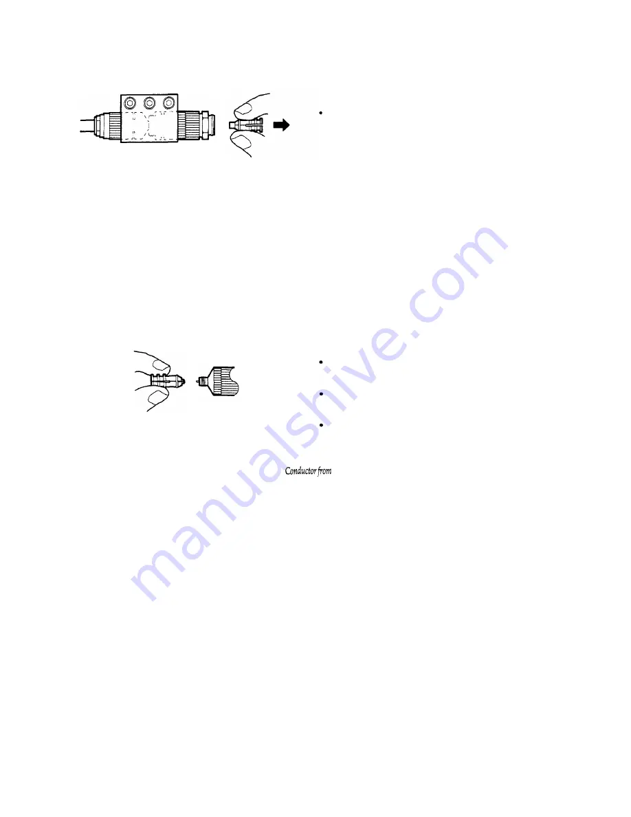
If the air line center conductor remains with the female
port, use the installation tool to remove it as follows:
Squeeze the tool and push it to engage the center
conductor.
Hold the tool close to the connector, squeeze the tool
without closing the slot, and pull the assembly away.
Use your fingers to remove the center conductor from the
tool.
Remove Center
Port 2
(if
necessary)
l
Carefully insert the center conductor back into the
installation tool, male end first.
21


