


Before removing the display assembly, follow these steps:
1.
Shut down the computer. If you are unsure whether the computer is off or in Hibernation, turn the
computer on, and then shut it down through the operating system.
2.
Disconnect all external devices connected to the computer.
3.
Disconnect the power from the computer by first unplugging the power cord from the AC outlet and
then unplugging the AC adapter from the computer.
4.
Remove the battery (see
Battery on page 46
).
5.
Disconnect the wireless antenna cables from the WLAN module (see
WLAN module on page 57
).
6.
Remove the keyboard (see
Keyboard on page 61
).
7.
Remove the switch cover (see
Switch cover on page 65
).
Remove the display assembly:
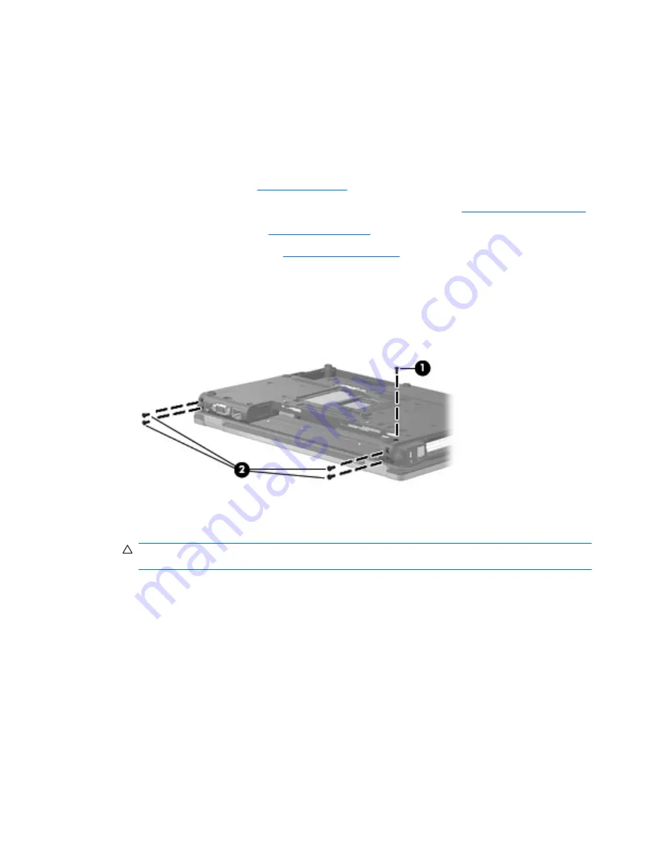
1.
Close the computer and turn it upside down, with the rear panel toward you.
2.
Remove the Torx T8M2.5×9.0 screw
(1)
that secures the display assembly to the computer.
3.
Remove the four Torx T8M2.5×9.0 screws
(2)
that secure the display assembly to the computer.
4.
Turn the computer right-side up, with the front toward you.
5.
Open the computer as far as possible.
CAUTION:
The display assembly will be unsupported when the left and right hinge cover screws
are removed. To prevent damage to the display assembly, support it before removing the screws.
6.
Remove the Phillips PM2.5×4.0 screw
(1)
that secures the left hinge cover to the computer.
7.
Remove the left hinge cover
(2)
. The display hinge covers are available using spare part number
486287-001.
8.
Disconnect the display panel cable
(3)
from the system board.
Component replacement procedures
75
Содержание 6530b - Compaq Business Notebook
Страница 1: ...HP Compaq 6530b Notebook PC and HP Compaq 6535b Notebook PC Maintenance and Service Guide ...
Страница 4: ...iv Safety warning notice ...
Страница 28: ...20 Chapter 3 Illustrated parts catalog ...
Страница 143: ...Where used 3 screws that secure the rear cover to the base enclosure Torx8 T8M2 5 9 0 screw 135 ...
Страница 146: ...Where used 4 screws that secure the system board bracket to the base enclosure 138 Chapter 7 Screw listing ...
Страница 148: ...Where used 2 screws that secure the rear cover to the base enclosure 140 Chapter 7 Screw listing ...
Страница 155: ...9 Connector pin assignments 147 ...
Страница 158: ...RJ 11 modem Pin Signal 1 Unused 2 Tip 3 Ring 4 Unused 5 Unused 6 Unused 150 Chapter 9 Connector pin assignments ...
Страница 175: ......


