


29
Prepare an IRF member ID assignment scheme. An IRF fabric uses member IDs to uniquely identify and
manage its members, and you must assign each IRF member switch a unique member ID.
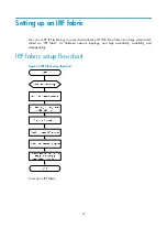
Planning IRF topology and connections
You can create an IRF fabric in daisy chain topology or more reliable ring topology. In ring topology, the
failure of one IRF link does not cause the IRF fabric to split as in daisy chain topology. Instead, the IRF
fabric changes to a daisy chain topology without interrupting network services.
You connect the IRF member switches through IRF ports, the logical interfaces for the connections
between IRF member switches. Each IRF member switch has two IRF ports: IRF-port 1 and IRF-port 2. To
use an IRF port, you must bind at least one physical port to it.
When connecting two neighboring IRF member switches, you must connect the physical ports of IRF-port
1 on one switch to the physical ports of IRF-port 2 on the other switch.
The HP 5130 EI switches can provide 10-GE IRF connections through SFP+ ports, and you can bind
several SFP+ ports to an IRF port for increased bandwidth and availability.
show the topologies of an IRF fabric containing three HP 5130-24G-4SFP+
EI/HP 5130-24G-4SFP+ EI TAA switches. The IRF port connections in the two figures are for illustration
only, and more connection methods are available.
Figure 34
IRF fabric in daisy chain topology
Figure 35
IRF fabric in ring topology


