
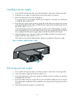
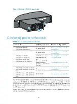
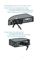


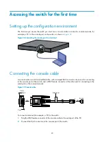


30
Identifying physical IRF ports on the member switches
Identify the physical IRF ports on the member switches according to your topology and connection
scheme.
Planning the cabling scheme
Use SFP+ cables or SFP+ transceiver modules and fibers to connect the IRF member switches. If the IRF
member switches are far away from one another, choose the SFP+ transceiver modules with optical fibers.
If the IRF member switches are all in one equipment room, choose SFP+ cables.
HP recommends that you use ring topology to connect the switches. The following describes cabling
schemes in ring topology.
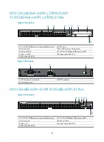
Connecting the IRF member switches in one rack
Use short-haul and long-haul SFP+ cables to connect the IRF member switches (9 switches in this example)
in a rack as shown in
. The switches in the ring topology (see
) are in the same order
as connected in the rack.


