20
6. SWITCHES
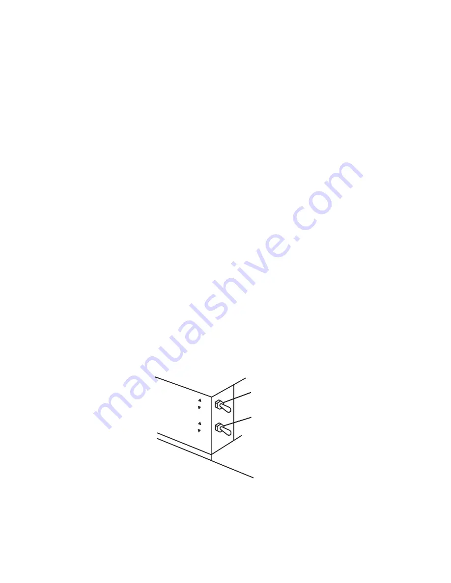
Two different control switches are used for operation of KM-100A and KM-125A. They
are located on the right side of the control box which becomes accessible when the front
louver is removed. The upper is the control switch, and the lower is the service switch.
[a] CONTROL SWITCH
This switch is used to place the machine into one of three modes: “OFF” (center
position), “ICE” (upper position), and “SERVICE” (lower position).
[b] SERVICE SWITCH
When the control switch is placed in the “SERVICE” position, power is supplied to the
service switch. The service switch can be used to perform two functions: draining the
tank (“DRAIN” = lower position) and washing the icemaking compartment (“WASH” or
“CIRCULATE” = upper or center position). Both the “WASH” and “CIRCULATE” positions
activate the same function of washing the icemaking compartment. The service switch is
activated in any of the three positions when the power is supplied to the pump motor.
1) “DRAIN”
KM-100A and KM-125A employ the pump-out drain system. When the service switch is
active and placed in the lower position, power is supplied to the pump motor and drain
valve.
2) “WASH” or “CIRCULATE”
When the service switch is active and placed in the upper or center position, power is
supplied to the pump motor. This function is to clean the evaporator plate.
Fig. 2
Control Switch
Service Switch
SERVICE
ICE
OFF
DRAIN
WASH
CIRCULA
TE
Содержание KM-100A
Страница 10: ...7 ...
Страница 25: ...22 2 WIRING DIAGRAM a PRODUCTION 2008 Auxiliary Code T 1 U 1 ...
Страница 26: ...23 b PRODUCTION 2009 Auxiliary Code U 1 OR LATER ...


