49
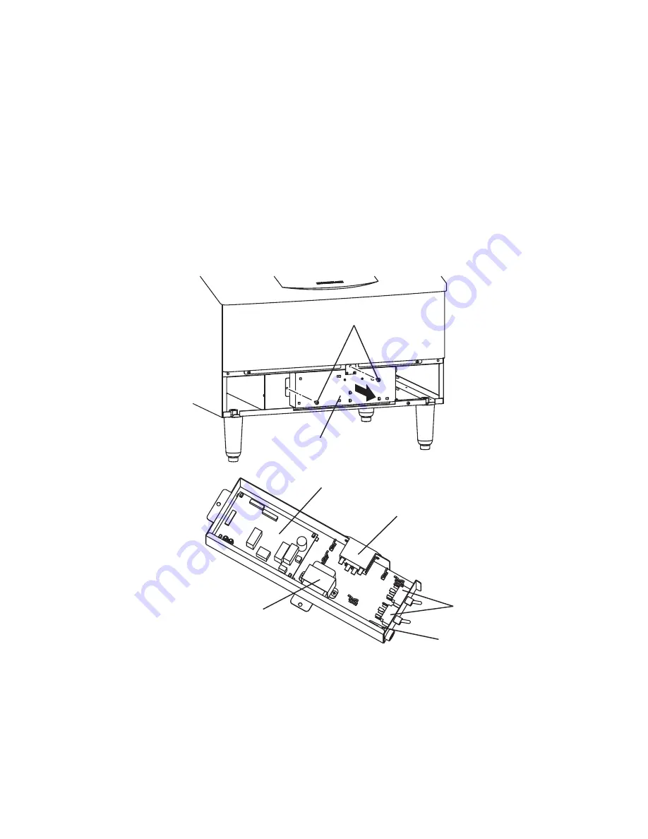
14. CONTROL BOX
1) Unplug the icemaker or disconnect the power source.
2) Remove the Louver.
3) Remove the two mounting screws, and pull the Control Box toward you.
4) Refit the removed parts in the reverse order of the removal procedure.
Note: After replacing the components inside the Control Box, connect and tie the wires
properly in their correct position. Especially make sure that the Harness does not
press the Push Buttons on the Control Board.
Fig. 15
Screw
Control Box
Power Relay
Transformer
Control Board
Power Switch
Fuse
Fuse Holder
Pull toward you
Содержание KM-100A
Страница 10: ...7 ...
Страница 25: ...22 2 WIRING DIAGRAM a PRODUCTION 2008 Auxiliary Code T 1 U 1 ...
Страница 26: ...23 b PRODUCTION 2009 Auxiliary Code U 1 OR LATER ...


