


MAN1175-01-EN
Indianapolis, USA | Cork, Ireland | Calgary, Canada | Bangalore, India | Oakleigh, Australia | Tianjin, China | Esteio, Brazil
Please visit our website for a complete listing and to learn more about certified Horner Automation products.
This document is the property of Horner Automation Group, and is subject to change.
page 3 of 8
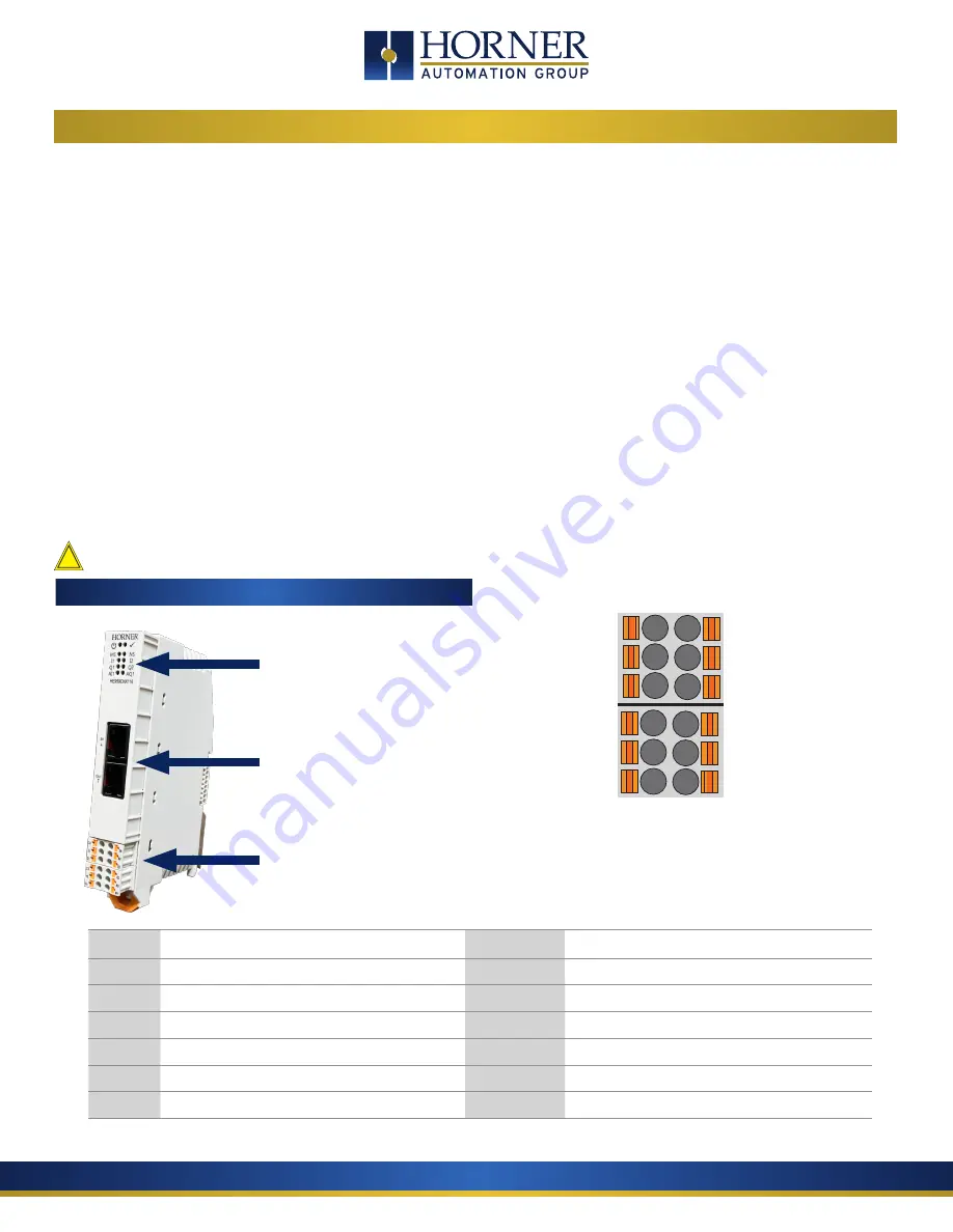
3 WIRING
The OCS-I/O HE959CNX16 Base should be powered independently from the power supplied to the OCS-I/O modules themselves. This
offers optimum noise immunity and helps maintain galvanic isolation between the CsCAN Network and I/O Power. The recommend-
ed approach is to power the CsCAN network from one power supply, and I/O devices from at least one separate power supply. The
OCSIO bases are powered from the CsCAN Network. Horner OCS controllers do not supply 24VDC to the V+ connection of the CsCAN
network.
To power the HE959CNX116, use bottom six pin connector.
For network wiring, the recommended approach is to daisy-chain each node, with a continuous connection for shield. The center pin
of the CAN port does not provide a connection to earth ground. The cable shield should be connected to earth ground at one location
only – usually at the DC supply powering the network. The network DC supply should have its V- terminal connected directly to earth
ground.
If multiple DC supplies are used to power the network, the V+ from any one supply should be connected only to nodes it is powering
– disconnected from other sections powered by other supplies. The V- connection should be continuous across the entire network,
although V- should connect to earth at exactly one point only.
At each end of the network, a 121
Ω
, 1/4W, 1% resistor should be used for termination – installed between the CAN_H and CAN_L ter-
minals. Only appropriate Thin (for <100m) or Thick (<500m) cabling should be used (assuming 125 KBaud) available from a variety of
sources. .
Use 75°C copper conductors only.
SIGNAL LABEL
DESCRIPTION
SIGNAL
LABEL
DESCRIPTION
AI1a
1a
Universal Analog Input “a”
AI1b
1b
Universal Analog Input “b”
AI1c
1c
Universal Analog Input “c”
GND
0V
Digital and Analog Ground
I1
I1
Digital / Analog Input 1
Q1
Q1
Digital Output 1
I2
I2
Digital / Analog Input 2
Q2
Q2
Digital Output 2
VEXT
V1
V+ Input for Digital Output
AQ1
AQ
Analog Output
24V
V+
V+ Input for Power
GND
0V
Digital and Analog Ground
1a *
1c *
I1
I2
V1
V+
1b *
0V
Q1
Q2
AQ
0V
Onboard Wiring
Onboard I/O
CAN Port - IN
CAN Port - OUT
LED Indicators
See page 6
*WARNING:
Do not put voltage on 1a and no more than
12V on 1b or 1c ports. Doing so will damage the board.
!


