Connecting a DCC Power Booster
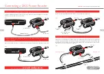
Using a Hornby R8236 RJ12 cable connect the booster to either of the two XpressNet ports of the Elite
controller or the XpressNet port of the Select.
Connecting to the Select and Elite using the XpressNet port
R 8236
RJ12 Cable
To isolated track
From PSU
Fig 1
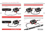
Connect 2 wires from the “Boost” terminals positioned on the back of the Elite to the terminals on the Booster.
Connecting the Elite using the “Boost” terminals located on the back
of the controller
To isolated track
From PSU
Fig 2
3
4
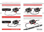
Connect the two output terminals from Booster A to the input terminals of Booster B.
Connecting two Boosters together
To isolated
track 2
To isolated
track 1
From PSU 2
From PSU 1
From Main Controller
Boost Output
Fig 3
If RJ12 Leads, or other suitable flex of sufficient length is not available, the Booster can take a Control signal directly
from the track of the main Power area. Connect the Power clips supplied, to the track as shown. The wire from
the main Power area should be connected to “Boost IN”. The wire from the Secondary Power area should be
connected to the “Track” terminals on the Booster.
Alternative connection
Isolated track
From PSU
Fig 4
For more information visit:
www.hornby.com
A
B
A
B
Please Note:
PSU = Power Supply Unit (Transformer)
Main power area
Secondary power area
Next Booster
Next Booster


