Honeywell VR8405 Скачать руководство пользователя страница 10

68-0150

10

VR8405

OPERATION

If main burner flame is restarted successfully, operation

continues as described above. Gas control operation is de-
scribed in more detail below.

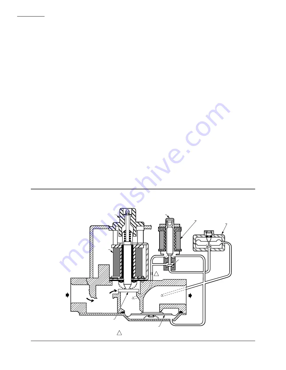
VALVE POSITION DURING THERMOSTAT OFF
CYCLE

Each valve is positioned as shown in Fig. 8 when the:
• Gas control knob is in the ON position.
• Thermostat is not calling for heat.
The first automatic valve is closed. The second automatic

valve operator is de-energized, closing the channel to the
pressure regulator, and opening a channel to the underside
of the second automatic valve operator valve diaphragm.
The combination of spring pressure under the second auto-
matic valve diaphragm and lack of outlet pressure hold the
diaphragm firmly closed. Main burner gas flow is blocked
by both valves.

WHEN THERMOSTAT CALLS FOR HEAT

When the thermostat calls for heat, the DI module gener-

ates a spark at the main burner and the first automatic valve
and second automatic valve operators are energized, Fig. 9.
The first automatic valve opens, and the second automatic
valve operator valve disc is lifted off its seat. This diverts
gas flow from the second automatic valve diaphragm, and
causes a reduction of pressure on the underside of this
diaphragm. The reduced pressure on the bottom of the auto-
matic valve diaphragm repositions the diaphragm down-
ward, away from the valve seat, allowing main burner gas
flow.

Standard-Opening Pressure Regulation (VR8405M)

During the ON cycle, the servo pressure regulator pro-

vides close control of outlet pressure, even if inlet pressure
and flow rate vary widely. Any outlet pressure change is
immediately reflected back to the pressure regulator dia-
phragm, which repositions to change the flow rate through
the regulator valve and, thus, through the automatic valve.

If outlet pressure begins to rise, the pressure regulator

diaphragm moves slightly higher, allowing less gas flow to
the gas control outlet. This increases gas pressure under the
automatic valve diaphragm and repositions the valve disc
closer to the seat. Thus, flow of gas through the second
automatic valve is reduced, and outlet pressure falls to the
desired level.

If outlet pressure begins to fall, the pressure regulator

diaphragm moves slightly lower, allowing more gas flow to
the gas control outlet. This decreases gas pressure under the
second automatic valve diaphragm and repositions the
valve disc further from the seat. Thus, gas flow through the
second automatic valve is increased, and outlet pressure
rises to the desired level.

Slow-Opening Pressure Regulation (VR8405H)

Slow-opening gas controls function the same as stan-

dard-opening models except that when the thermostat calls
for heat, the second automatic valve opens gradually. Open-
ing is slowed because a flow restrictor in the passage from
the second automatic operator slows the rate at which gas
pressure is reduced under the second automatic valve dia-
phragm after the second automatic operator opens. Outlet

FIRST 
AUTOMATIC
VALVE 
SOLENOID

CONTROL
KNOB

GAS 
CONTROL 
INLET

SECOND AUTOMATIC
VALVE OPERATOR

SECOND 
AUTOMATIC
OPERATOR 
SOLENOID

SECOND 
AUTOMATIC
OPERATOR 
VALVE DISC

SERVO PRESSURE 
REGULATOR

GAS 
CONTROL 
OUTLET

SECOND AUTOMATIC
VALVE DIAPHRAGM  

FIRST AUTOMATIC VALVE

NOTE:  AUTOMATIC VALVE OPERATOR AND SERVO 
PRESSURE REGULATOR SHOWN OUTSIDE GAS 
CONTROL FOR EASE IN TRACING GAS FLOW.

SLOW-OPENING GAS CONTROL HAS A GAS FLOW RESTRICTOR IN THIS PASSAGE.

M9114

1

1

Fig. 8—Position of gas control components during thermostat Off cycle. Both valves positioned the
same; one valve shown for simplicity.

Содержание VR8405

Страница 1: ...t3 hour 20 3 meters3 hour Minimum capacity rated 200 feet3 hour 5 7 meters3 hour Solenoid operated dual first automatic valves open on thermostat call for heat and close when call for heat ends Diaphragm operatedsecondautomaticvalvesopen under control of the regulator and close if gas or power supply is interrupted Two position gas control knobs have ON and OFF positions All adjustments and wiring...

Страница 2: ...e ordering number or specify 1 Order Number 2 Natural or LP gas 3 Step pressure on VR8405P 4 Accessories is desired 5 Order separately transformer igniter sensor module limit controller and thermostat or controller as required If you have additional questions need further information or would like to comment on our products or services please write or phone 1 Your local Honeywell Home and Building...

Страница 3: ...ravity natural gas at 0 25 kPa pressure drop PRESSURE REGULATION Not adjustable DIMENSIONS See Fig 1 TEMPERATURE RATING VR8405H 0 F to 175 F 18 C to 79 C VR8405M P 40 F to 175 F 40 C to 79 C PRESSURE TAPPING Inlet and outlet taps standard Taps accessible from top of control Tap is 1 8 in NPT with plug containing recess for 3 16 in Allen wrench PRESSURE RATING AGA rating 1 2 psi 3 5 kPa inlet press...

Страница 4: ...e appliance manufacturer instructions if avail able otherwise use the instructions provided below INSTALL BUSHINGS ON ENTIRE GAS CONTROL 1 Remove seals over gas control inlet or outlet 2 Apply moderate amount of good quality pipe com pound to bushing leaving two end threads bare On an LP gas installation use compound resistant to LP gas See Fig 3 Do not use Teflon tape 3 Insert bushing in entire g...

Страница 5: ...ENGTH IN IN Pipe Size Thread Pipe This Amount Maximum Depth Pipe Can Be Inserted Into Control 3 4 13 16 3 4 1 1 1 16 1 5 Remove seals over gas control inlet and outlet if necessary 6 Connect pipe to gas control inlet and outlet Use a wrench on the manifold rather than on the gas control Refer to Figs 4 and 5 WIRING Follow the wiring instructions furnished by the appli ance manufacturer if availabl...

Страница 6: ... VALVE GND TEMPERATURE CONTROLLER POWER SUPPLY PROVIDE DISCONNECT MEANS AND OVERLOAD PROTECTION AS REQUIRED ALTERNATE LIMIT CONTROLLER LOCATION MAXIMUM IGNITER SENSOR CABLE LENGTH 3 ft 9 m OR LESS 3 A REPLACEABLE FUSE ALARM TERMINAL PROVIDED ON SOME MODELS M8051 MVPV MVPV L1 HOT L2 1 2 1 2 3 VR8405 COMBINATION GAS CONTROL Q347 IGNITER SENSOR BURNER 4 4 5 IGNITER SENSOR AND BURNER GROUND 3 5 ALARM ...

Страница 7: ... leak is detected tighten the pipe connection 3 Stand clear while lighting main burner to prevent injury caused from hidden gas leaks that could cause flash back in the appliance vestibule Turn on the entire gas control and light the main burner as described below 4 With the main burner in operation paint all pipe joints and gas control inlet and outlet with a rich soap and water solution 5 Ifanot...

Страница 8: ...ustable Step Opening Pressure Regulator 1 The gas control outlet pressure should match the manifold pressure listed on the appliance nameplate 2 With the main burner operating check the gas con trol flow rate using the meter clocking method 3 If desired flow rate is not as stamped on the control check the inlet pressure using a manometer at inlet pres sure tap or upstream of the gas control Regula...

Страница 9: ...nce these environments can cause the gas control to deteriorate more rapidly the system should be checked more often If the gas controls will be exposed to high ammonia conditions e g those used in greenhouses or animal barns contact your Honeywell sales representative to request a gas control with corrosion resistant construction The entire gas control should be replaced if It does not perform pr...

Страница 10: ... repositions to change the flow rate through the regulator valve and thus through the automatic valve If outlet pressure begins to rise the pressure regulator diaphragm moves slightly higher allowing less gas flow to the gas control outlet This increases gas pressure under the automatic valve diaphragm and repositions the valve disc closer to the seat Thus flow of gas through the second automatic ...

Страница 11: ...operators close bypassing the regulator s and shutting off the main burner As pres sure inside the gas controls and underneath the automatic valvediaphragmsequalize springpressureclosesthesecond automatic valves to provide a second barrier to gas flow Fig 9 Position of gas control components during burner on cycle Both valves are positioned the same one valve shown for simplicity two main valves a...

Страница 12: ...appliance The information below will be of assistance in a typical control application but the specific controls used and the procedures outlined by the manufac turer of your appliance may differ and require special instructions TO TURN ON THE APPLIANCE STOP READ THE WARNING ABOVE The lighting sequence of this appliance is automatic Do not attempt to manually light the main burner If the appli anc...

Отзывы: