background image

69-0814—1

6

4. With the main burner in operation, paint all pipe

joints and gas control inlet and outlet with a rich soap and
water solution.

5. If another gas leak is detected, tighten pipe connections.
6. Replace the part if gas leak cannot be stopped.

TURN ON GAS CONTROL

Rotate the gas control knobs counterclockwise

to

ON.

TURN ON MAIN BURNER

Follow instructions provided by appliance manufac-

turer or turn up thermostat to call for heat.

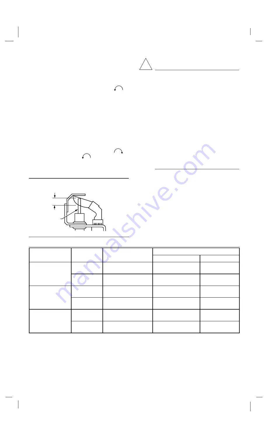
ADJUST THE PILOT BURNER FLAME

The pilot flame should envelop 3/8 to 1/2 inch [10 to

13 millimeters] of the igniter-sensor tip. Refer to Fig. 8. To
adjust the pilot flame.

1. Remove the pilot adjustment cover screw. Refer to

Fig. 3.

2. Turn the inner adjustment screw clockwise

to

decrease or counterclockwise

to increase the pilot

flame.

3. To prevent gas leakage replace the cover screw after

adjustment.

Fig. 8—Proper flame adjustment.

CHECK GAS INPUT TO MAIN BURNER

CAUTION

1. Do not exceed the input rating stamped on the

appliance nameplate, or manufacturer recom-
mended burner orifice pressure for the size
orifice(s) used. Make certain the primary air
supply to the main burner is properly adjusted
for complete combustion (refer to the appli-
ance manufacturer instructions).

2. WHEN CHECKING GAS INPUT BY

CLOCKING THE GAS METER:
• Make sure that the only gas flow through

the meter is that of the appliance being
checked.

• Make certain that other appliances are turned

off with pilot burners extinguished (or de-
duct that gas consumption from the meter
reading).

• Convert the flow rate to Btuh as described in

the Gas Controls Handbook, form 70-2602,
and compare to the Btuh input rating on the
appliance nameplate.

Standard-Opening and Slow-Opening Pressure
Regulator

1. The gas control outlet pressure should match the

manifold pressure listed on the appliance nameplate.

2. With the main burner operating, check the gas con-

trol flow rate using the meter clocking method.

3. If the desired gas flow rate is not as stamped on the

control, check the gas control inlet pressure using a ma-
nometer at the inlet pressure tap. Regulators are fixed. They
are not adjustable
. If the inlet pressure is in the normal
range (refer to Table 3), replace the entire gas control.
Otherwise, take the necessary steps to provide proper gas
pressure to the gas control.

!

TABLE 3—PRESSURE REGULATOR SPECIFICATION PRESSURES IN IN. WC [kPa].

Factory Set Outlet Pressure

Model

Type of Gas

Nominal Inlet Pressure

Step

Full Rate

H (Slow-opening)

Natural

7.0 [1.7]

3.0 - 5.0

[0.7 - 1.2]

LP

14.0 [3.9]

8.0 - 12.0

[2.0 - 3.0]

M (Standard)

Natural

7.0 [1.7]

3.0 - 5.0

[0.7 - 1.2]

LP

14.0 [3.9]

8.0 - 12.0

[2.0 - 3.0]

P (Step-opening)

Natural

7.0 [1.7]

0.7, 0.9, 1.2, 1.7,

[0.17, 0.22, 0.30, 0.42]

3.0 - 5.0

[0.7 - 1.2]

LP

14.0 [3.9]

1.4, 2.5, 4.0, 5.5

[0.35, 0.62, 1.0, 1.4]

8.0 - 12.0

[2.0 - 3.0]

NOTE: Factory set outlet pressure is not field adjustable.

PROPER FLAME 
ADJUSTMENT

IGNITER-
SENSOR 

M3080A

3/8 TO 1/2 INCH
[10 TO 13 mm]

Содержание VR8404

Страница 1: ...e drop 37 3 MJ meter3 0 64 specific gravity natural gas at 0 25 kPa pressure drop Use conversion factors in Table 1 to convert capacities for other gases TABLE 1 GAS CAPACITY CONVERSION FACTORS Gas Specific Gravity Multiply Listed Capacity By Manufactured 0 60 0 516 Mixed 0 70 0 765 Propane 1 53 1 62 ELECTRICAL RATINGS Voltage and Frequency 24 Vac 60 Hz 50 60 Hz models available on request Current...

Страница 2: ...Teflon tape 3 Insert bushing in entire gas control and thread pipe carefully into bushing until tight CHOOSE GAS CONTROL LOCATION Locate the gas control in the appliance vestibule on the gas manifold In replacement applications locate the entire gas control in the same location as the old gas control Do not locate the entire gas control where it can be affected by steam cleaning high humidity drip...

Страница 3: ...mpound resis tant to LP gas Refer to Fig 2 5 Remove seals over gas control inlet and outlet if necessary 6 Connect pipe to gas control inlet and outlet Use a wrench on the manifold rather than on the gas control Refer to Figs 3 and 4 Fig 2 Use moderate amount of pipe compound Pipe Size Thread Pipe This Amount Maximum Depth Pipe Can Be Inserted Into Control 3 4 13 16 3 4 1 1 1 16 1 Fig 3 Top view o...

Страница 4: ...f available or use the general instructions provided Fig 5 Always use new compression fitting Fig 6 VR8404 wiring connections in intermittent ignition system with S86 24V 2 24V 1 GND S86F H S860D MV MV MV PV MV PV PV PV GND BURNER 4 1 1 1 2 3 4 2 3 3 L1 HOT L1 HOT L2 L2 THERMOSTAT OR CONTROLLER LIMIT CONTROLLER VR8404 GAS CONTROL PILOT BURNER GROUND PILOT GAS SUPPLY Q345 Q364 Q348 Q362 Q381 PILOT ...

Страница 5: ...as control knobs will not operate by hand call a qualified service technician to replace the entire gas control 3 Both knobs must be in the same position for operation or shutoff GAS CONTROL KNOBS SETTINGS The gas control knobs have two settings OFF Prevents pilot and main burner gas flow ON Permits gas to flow into the control body Under control of the thermostat and intermittent pilot module gas...

Страница 6: ...the appliance being checked Makecertainthatotherappliancesareturned off with pilot burners extinguished or de duct that gas consumption from the meter reading Convert the flow rate to Btuh as described in the Gas Controls Handbook form 70 2602 and compare to the Btuh input rating on the appliance nameplate Standard Opening and Slow Opening Pressure Regulator 1 The gas control outlet pressure shoul...

Страница 7: ... INJURY OR DEATH Do not disassemble the gas control or either valve They contain no replaceable components Attempted disassembly or repair can damage the gas control Regular preventive maintenance is important in applica tions such as commercial cooking agricultural and indus trial operations that place a heavy load on system controls because In many such applications particularly commercial cooki...

Страница 8: ...sion 5 Call a qualified service technician to replace the entire gas control if it has been flooded with water 6 Replace the entire gas control in the event of any physical damage tampering bent termi nals missing or broken parts stripped threads or evidence of exposure to heat IMPORTANT Follow the operating instructions pro vided by the manufacturer of your heating appliance The information below...

Отзывы: