background image

VR8245 AND VR8345 UNIVERSAL ELECTRONIC IGNITION GAS CONTROLS

5

69-2013

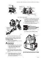
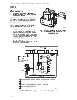
Fig. 3. Top view of gas control.

Fig. 4. Proper use of wrench on gas control.

Connect Pilot Gas Tubing (Intermittent 

Pilot Ignition Only)

1.

Remove the pilot gas seal (plug).

2.

Cut tubing to desired length and bend as necessary 
for routing to pilot burner.

CAUTION

Do not kink tubing.

1. Do not make sharp bends or deform the tubing.
2. Do not bend tubing at the gas control or pilot 

burner after compression fitting has been 
tightened because this can result in gas 
leakage at the connection.

3.

Square off and remove burrs from end of tubing.

4.

Use the compression fitting supplied with this gas 
control. Slip the fitting over the tubing and slide out 
of the way.

NOTE: When replacing a gas control, cut off old com-

pression fitting and replace with the new com-
pression fitting provided on the gas control. 
Never use the old compression fitting because it 
may not provide a gas-tight seal.

5.

Push tubing into the pilot gas tapping on the outlet 
end of the control until it bottoms. While holding tub-
ing all the way in, slide compression fitting into 
place, engage threads and turn until finger tight. 
Then tighten one more turn with wrench. Do not 
overtighten. Refer to Fig. 5 and 6.

6.

Connect other end of tubing to pilot burner accord-
ing to pilot burner manufacturer instructions.

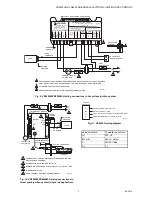
Fig. 5. Always use new compression fitting.

Fig. 6. Remove pilot gas seal (plug) and install pilot 

gas tube for intermittent pilot application on VR8345.

INLET

INLET

OUTLET

H I

L O

O U T L E T

P R E S S U R E  

T A P

P IL O T   O U T L E T

PRESSURE REGULATOR 

ADJUSTMENT

(UNDER CAP SCREW)

WIRING

TERMINALS (3)

INLET

PRESSURE TAP

PILOT ADJUSTMENT

()UNDER CAP SCREW)

GAS

CONTROL

KNOB

HI-LOW 

ADJUSTMENT SCREWS

(UNDER CAP)

REGULATOR

VENT COVER

TWO-STAGE

PRESSURE

REGULATOR

MODEL

M10968B

APPLY WRENCH 

FROM TOP OR 

BOTTOM OF GAS 

CONTROL TO 

EITHER SHADED AREA

M8562B

GAS CONTROL

TIGHTEN NUT ONE TURN

BEYOND FINGER-TIGHT.

TO PILOT

BURNER

FITTING BREAKS OFF AND CLINCHES

TUBING AS NUT IS TIGHTENED.

M3076B

M8441A

PV

MV

PV

MV

OFF 

ON 

PILOT GAS 

TUBE

Содержание VR8245

Страница 1: ...e conversion factors in Table 2 to convert capacities for other gases APPROVALS American Gas Association Design Certificate L2025007 Canadian Gas Association Design Certificate L2025007 PIPE ADAPTERS Includes two 3 4 to 1 2 inch NPT bushings and one 1 2 to 3 8 inch NPT bushing CROSS REFERENCE See Table 4 for cross reference information INSTALLATION WHEN INSTALLING THIS PRODUCT 1 Read these instruc...

Страница 2: ...ressure Regulator Type Current Draw A Conversion Kits Natural Gas LP LP Natural Gas VR8245M 1 2 x 1 2 Standard 5 393691 394588 VR8345H 3 4 x 3 4 Slow Opening 7 393691 394588 VR8345M 3 4 x 3 4 Standard 7 393691 394588 VR8345Q 3 4 x 3 4 2 Stage 9 396021 396025 Table 4 Cross Reference Universal Replacement Cross Reference Universal Service Part Honeywell White Rodgers Robert Shaw VR8245M2530 VR8204A1...

Страница 3: ... over gas control inlet or outlet 2 Apply moderate amount of good quality pipe com pound to bushing leaving two end threads bare See Fig 1 3 Insert bushing in gas control and carefully thread pipe into the bushing until tight Fig 1 Use moderate amount of pipe compound Location Locate the combination gas control in the appliance vestibule on the gas manifold In replacement applications locate the g...

Страница 4: ...diment trap 4 Apply a moderate amount of good quality pipe com pound do not use Teflon tape to pipe only leaving two end threads bare See Fig 1 On LP installa tions use compound resistant to LP gas 5 Remove seals over gas control inlet and outlet if necessary 6 Connect pipe to gas control inlet and outlet Use wrench on the square ends of the gas control See Fig 3 and 4 When working with an intermi...

Страница 5: ...de a gas tight seal 5 Push tubing into the pilot gas tapping on the outlet end of the control until it bottoms While holding tub ing all the way in slide compression fitting into place engage threads and turn until finger tight Then tighten one more turn with wrench Do not overtighten Refer to Fig 5 and 6 6 Connect other end of tubing to pilot burner accord ing to pilot burner manufacturer instruc...

Страница 6: ... Connect control circuit to gas control terminals See Fig 3 and 8 9 or 10 4 Adjust the thermostat heat anticipator to 0 7 the rat ing stamped on the valve operator Fig 7 Install wire adapter for hot surface or direct spark ignition systems Pilot plug must be in the valve pilot opening Fig 8 VR8245M VR8345M H wiring connections in intermittent ignition system M8440A PV M V PV M V OFF ON PILOT GAS S...

Страница 7: ... 0 2 VALVE LOAD 120VAC HOT 570A0056 WARNING Explosion hazard Can cause serious injury or death This device can malfunction if it gets wet Never try to use a device that has been wet replace it GND BURNER 24V GND VALVE GND 24V LED L2 HSI HSI L1 SENSE VALVE MPLS MN 55422 SEE INSTRUCTIONS FOR REMOTE SENSE DUAL ROD APPLICATIONS TRIAL TIME NUM OF TRIALS CONFIGURATION PLUG 120VAC NEUTRAL TRIAL TIME 7 SE...

Страница 8: ...er solution anytime work is done on a gas control Gas Leak Test 1 Paint all pipe connections upstream of the gas con trol with a rich soap and water solution Bubbles indicate a gas leak 2 If a gas leak is detected tighten the pipe connection CAUTION Fire or explosion hazard Stand clear while lighting main burner to prevent injury caused from hidden gas leaks that could cause flashback in the appli...

Страница 9: ... burner lightoff Make sure that the main burner lights smoothly and that all ports remain lit 2 Check the full rate manifold pressure listed on the appliance nameplate Gas control full rate outlet pressure should match this rating 3 With main burner operating check the control flow rate using the meter clocking method or check pres sure using a manometer connected to the outlet pressure tap on the...

Страница 10: ...e to the safety shutdown or safety lockout tests recommended for the intermittent pilot IP hot surface HSI or direct spark DSI module When different use the procedure rec ommended for the module 1 Turn off gas supply 2 Set the thermostat or controller above room temperature to call for heat 3 Intermittent Pilot Ignition Watch for an igni tion spark at pilot burner either immediately or following p...

Страница 11: ...s that are used seasonally should be checked before shutdown and again before the next use Consequence of unexpected shutdown Where the cost of an unexpected shutdown would be high the system should be checked more often Dusty wet or corrosive environment Since these environments can cause the gas control to deteriorate more rapidly the system should be checked more often NOTE If the gas control w...

Страница 12: ...ge tampering bent terminals missing or broken parts stripped threads or evidence of exposure to heat IMPORTANT Follow the operating instructions provided by the manufacturer of your heating appliance The information below will be of assistance in a typi cal gas control application but the specific con trols used and the procedures outlined by the manufacturer or your appliance may differ and requi...

Отзывы: