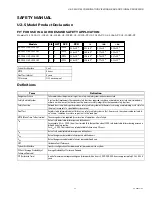
U2-S MODEL COMBINATION VIEWING HEAD AND SIGNAL PROCESSOR
32-00015—05
6
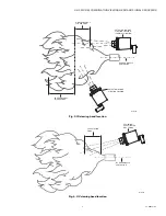
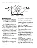
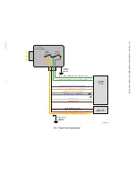
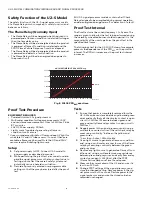
Fig. 5. Sighting opposed fired burners.
Mounting Accessories
1.
Cable assemblies for quick disconnect models are
listed below. All are ITC/CIC approved, and meet
IP67 at connector when properly installed.
• ASYU2S molded connector with 50 foot cable.
• ASYU2S-100 molded connector with 100 foot
cable.
• ASYU2-200 molded connector with 200 foot
cable.
• ASYU2-300 molded connector with 300 foot
cable.
2.
Fiber Optic System - The U2 models are compatible
with the Honeywell FASA Glass or Quartz fiber optic
extension. Refer to Honeywell manual 69-2683
3.
U2-S supports Modbus protocol. The system can be
monitored using user's hardware and software
and/or Honeywell FlameTool for PC or Honeywell
FlameTool for Panel (S7999). For detail refer to man-
ual 32-00001 and 32-00003.
4.
There are several mounting accessories available
from Honeywell. Please check with your sales person
for detail.
a. R-518-PT12 (Ultem Iso PT Adapter)
b. R-518-PT12L (Ultem Iso PT Adapter with lens)
c. R-518-CL12-PG (Purge Air Coupler 1" NPTM &
1/2" NPTF)
d. M-701-2 (Swivel Mount)
e. R-518-CL12-HTG (Locking Coupler).
OPERATION
Available sensors continuously convert flame radiation to
a magnitude displayed on the U2 display. The displayed
value described further as "flamecount" is the sum of all
active sensor readings.
If flame count is greater than the flame on setpoint for
longer than the time delay, a flame on condition is realized
and the flame relay contacts are closed. The flame relay
contacts remain closed until the flame count falls below
the flame off setpoint for longer than the flame failure
response time, at which a flame off condition is realized
and the flame relay contacts are opened. Periodic self
check performs fault detection, and if a fault is detected,
both the flame relay and self check relay contacts are
opened.
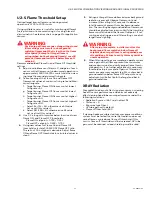
While File Input Select is low, file parameters defined at
Modbus register 40093 are used to determine flame relay
state. While file input select is high (+24V), file 1 parameter
settings are used to determine flame relay state.
File Select Output provides feedback to indicate the state
of the file input select. See chart below:
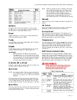
There are several parameter adjustments that permit
configuration of each sensor. .
A touch wheel located at the back of the viewing head
provides access to parameters for adjustment and
configuration. The configuration menu is simple and easy
to follow. Full character, 4-digit, scrolling LED displays are
visible in the dark or sunlight. Individual sensor LEDs
(model dependent 1, 2, or 3 total located below the
display) flash to indicate the output of each sensor (green
= UVTron, Blue = SSUV, Red = IR). The upper right green
self-check LED provides indication, and status of the self
check. The upper left red "Flame On" LED provides status
of the flame relay.
NOTE:
The number of LEDs are model dependent.
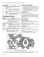
The touch wheel is designed like an iPod™ to allow for slow
or fast changes by moving a finger slower or faster around
the back glass. Alternatively, the user may tap
←
(-) or
→
(+) to make changes. Swirl finger at touchwheel > 360
degrees and release to enter the menu. Tap
ENTER/STORE to store selected data. Tap BACK to return
to the previous menu. Exiting all of the menus will display
the current flame count.
VIEWING HEAD
BURNER NOZZLE
NO. 1
NO. 1 FLAME
ENVELOPE
NO. 2 FLAME
ENVELOPE
VIEWING HEAD
BURNER
NOZZLE NO. 2
HIGH FREQUENCY
IR ZONE
LOW FREQUENCY
ZONE (LESS THAN
36HZ)
HIGH FREQUENCY
IR ZONE
M33287B
File Input Select Value
File Select Output Value
0V
0V
24V
24V

