U2-S MODEL COMBINATION VIEWING HEAD AND SIGNAL PROCESSOR
3
32-00015—05
PF version
General
FM, CSA, CE (EN298), and EAC
Hazardous Location
CSA
CLASS I, DIVISION 1, GROUPS A, B, C, D
CLASS II, DIVISION 1, GROUPS E, F, G
CLASS III DIVISION 1 T6
Ex d IIC T6 Gb Ex tb IIIC T85°C Db
CLASS I, ZONE 1, AEx d IIC T6 Gb
ZONE 21 AEx tb IIIC T85°C Db
IECEx SIR 15.0068X Ex db IIC T6 Gb
Ex tb IIIC T85°C Db IP66
SIRA 15ATEX1192X Ex db IIC T6 Gb
Ex tb IIIC T85°C Db IP66
CAUTION
CAUTION
!
Possible Equipment Damage
The aluminum surface of the U2 may store an
electrostatic charge and become a source of
ignition in applications with a low (<30%) relative
humidity. Cleaning the surface should only be
done with a damp cloth.
CAUTION
CAUTION
!
Do not expose to acetone, gasoline, hexane, or
ethyl acetate. label is not approved for these
chemicals.
Wiring
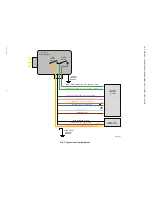
See “Typical Installation Diagram.” on page 12.
*Note - pink wire unused, leave unconnected.
CAUTION
CAUTION
!
Check wiring before applying power to the
system to make sure it is in accordance with the
wiring chart. Incorrect wiring may result in
unsafe operation or damage to U2.
NOTES:
1.
For remote configuration and monitoring, refer
to Honeywell manuals for FlameTool for PC
(32-00001-01) and HMI S7999 Panel (32-
00003-01).
2.
A total of eight parameter files are available.
Files 2 through 7 may be accessed using Fla-
metools, and configured using Modbus regis-
ter 40093.
INSTALLATION
BELGIUM
Maxon International BVBA
Luchthavenlaan 16-18
1800 Vilvoorde, Belgium
Tel: 32.2.255.09.09
Fax: 32.2.251.82.41
See “Typical Installation Diagram.” on page 12.
Installation should be carried out by a qualified engineer
and should meet all local standards and safety
requirements.
Hazardous location installations require the use of
ITC/CIC approved cable installed in cable tray for non-PF
models, and in metal conduit for -PF models. The cable
installation must conform to the latest revision of the
National Electrical Code, or Canadian Electrical Code for
Class I, Division 2 (non-PF models), or for Class I, Division
1 (-PF models).
WARNING
WARNING
WARNING
Approved CLI, DIV1 conduit seal must be
installed at PF model enclosure fitting for CLI,
DIV1 hazardous location use.
Non-PF models must be secured as follows: hand-tighten
the connector at viewing head until it can be turned no
more. Continue tightening the connector an additional
180 degrees using pliers, or similar tool. Verify that
connector cannot be loosened by hand.
Non-PF/
Color
Function
Connection
1-Red
Power 24 VDC
Connect to 22-26 VDC
To power supply
positive terminal
2-Purple
File Select Input, 0 or 1
To control output. >21V
input = file 1,
<16V = active file
defined at Modbus
register 40093(default
0).
3-Orange
mA output (+)
To current meter
positive
4-Blue
mA output (-)
To current meter
negative
5-Black
Power Supply Return (-) or 0 VDC
To Power Supply
negative terminal.
6-Yellow
Flame Relay (NO)
(power in)
To flame/fault relay
power source
7-Green
Fault Relay (NO) (fault output)
To fault monitoring of
burner control system
8-Grey
Flame Relay (NO)
(safety output)
To burner control
system
9-Tan
File Select Output, 0 or +24V
output. Feedback for system
controlling file input select.
To burner control
system. 0V = File Select
Input is low, or +24V if
FileSelect Input is high.
10-White
+RS485 Modbus
To
11-Drain
Cable Overall Shield
To Earth Ground
12-Brown
-RS485 Modbus
To Modbus -
Non-PF/
Color
Function
Connection

