Honeywell U2-1010S Скачать руководство пользователя страница 4

U2-S MODEL COMBINATION VIEWING HEAD AND SIGNAL PROCESSOR

32-00015—05

4

WARNING

WARNING

WARNING

Over-tightening the connector can damage the 
connector or housing.

Damage will void warranty and hazardous location 
approvals. Do not exceed 180 degrees of further 
rotation after hand tightening!

WARNING

WARNING

WARNING

EXPLOSION HAZARD
DO NOT DISCONNECT WHILE CIRCUIT IS LIVE 
UNLESS AREA IS KNOWN TO BE 
NONHAZARDOUS.

Substitution of components may impair suitability 
for class i, division 2.

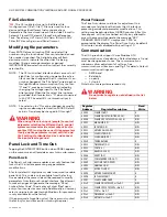
The U2-S model viewing port is designed for interface to a 
1" NPT (M) fitting. The viewing head can be mounted in 
any orientation, any angle, upward or downwards.

It is recommended that earth ground is applied at the 
labeled earth ground screw connection on the housing. It 
is recommended the drain wire be connected to earth at 
power supply. 

To reduce noise interference from ignition transformer or 
other high voltage sources, make sure all high voltage 
cables are in good condition and are at least 300 mm (12") 
away from U2 wiring.

Location/Mounting on Burner

Honeywell can provide mounting accessories such as a 
swivel mount, heat/electrical insulator, quick mechanical 
disconnect, high pressure isolation unit, etc. Check with 
your sales representative for your application.

1.

Ensure location provides clear view of the flame 
under all operating conditions.

2.

If the burner is provided with a pipe mount, use a bell 
type reducer to 1" NPT (M).

3.

When using purge/cooling air, make sure hoses are 
electrically isolated from the Earth to prevent multi-
ple ground loops.

4.

Depending upon the application, purge/cooling air 
pressure and flow will be different. As it is easier to 
measure pressure than flow, ensure that the 
entrance to air connection is a minimum of 25 mm 
WC (1" wc) above back pressure at all the time, from 
minimum to maximum load.

5.

IMPORTANT! 
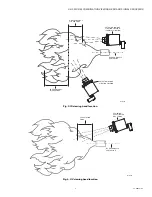
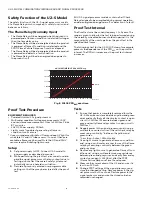
FLAME DISCRIMINATION
In multi-burner applications, it is important to sight 
for high frequency, high radiation intensity zone of 
the target flame, while sighting the low frequency, 
low radiation intensity zone of the background flame 
see Fig. 3 for IR, or Fig. 4 for UV for an example. This 
allows for filter, gain, and threshold settings to prop-
erly discriminate or recognize the target flame while 
rejecting background flame. 

6.

Where practical, use a swivel mount to allow for 
adjustments to optimize the flame viewing location.

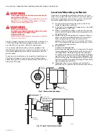
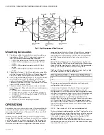
Fig. 1. Dimensional drawings.

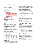
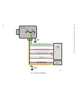
Fig. 2. Typical mounting example.

3/4 (19) NPT

CONNECTION

2-29/32 (73)

1(25)

1 (25) NPT

CONNECTION

5-3/32 (130)

4-19/32

(118)

M34431

R-518-CL12-PG

PURGE AIR COUPLER

AND R-518-PT12 

INSULATING LOCKING

COUPLER ADAPTER 

BURNER FRONT PLATE

OR WINDOWBOX

M33628

1 (25) 

NPTF PIPE

FLANGE

(OPTIONAL)

Содержание U2-1010S

Страница 1: ...and Recycling Waste electrical products should not be disposed of with general waste Please recycle where these facilities exist Check with your local authority for recycling advice GENERAL INFORMATION The Honeywell U2 101xS series model is a viewing head and signal processor in a single enclosure intended for use with a burner control system in Industrial Flame Monitoring applications There are s...

Страница 2: ... resettable for power source and Flame Relay Maximum furnace back pressure 35 Kg Cm2 500 PSI Selectable Flame Failure Response Time FFRT 1 2 3 seconds Error 0 0sec 0 5sec Internal Temperature Indication Degrees C or F in dis play menu of U2 or available at Modbus register 40019 Self Checking Internal electronic self checking is performed once per second to verify that system is operating properly ...

Страница 3: ...rried out by a qualified engineer and should meet all local standards and safety requirements Hazardous location installations require the use of ITC CIC approved cable installed in cable tray for non PF models and in metal conduit for PF models The cable installation must conform to the latest revision of the National Electrical Code or Canadian Electrical Code for Class I Division 2 non PF model...

Страница 4: ...entative for your application 1 Ensure location provides clear view of the flame under all operating conditions 2 If the burner is provided with a pipe mount use a bell type reducer to 1 NPT M 3 When using purge cooling air make sure hoses are electrically isolated from the Earth to prevent multi ple ground loops 4 Depending upon the application purge cooling air pressure and flow will be differen...

Страница 5: ...ation Fig 4 UV viewing head location DETECTOR IN GOOD SIGHTING POSITION PARALLEL SIGHTING BURNER NOZZLE CENTERLINE DETECTOR IN POOR SIGHTING POSITION LOW FREQUENCY FLICKER ZONE HIGH FREQUENCY FLICKER ZONE M33285B UV VIEWING HEAD SIGHTED ON UV ZONE BURNER NOZZLE CENTERLINE UV RADIATION ZONE M33286B ...

Страница 6: ...ition is realized and the flame relay contacts are opened Periodic self check performs fault detection and if a fault is detected both the flame relay and self check relay contacts are opened While File Input Select is low file parameters defined at Modbus register 40093 are used to determine flame relay state While file input select is high 24V file 1 parameter settings are used to determine flam...

Страница 7: ...g the MA gain does not alter gain settings of UVTron SSUV or IR After completing flame setpoint configuration adjustment to the MA gain may be used to set MA output at full system load Flame On Threshold Setting Displays the current Flame On threshold settings It is important to note that flame count must reach this threshold in order for the flame relay to energize After the flame relay is energi...

Страница 8: ... A factory default 4 digit access code is required to enable panel lock This code is only available from the factory Once enabled the same code will be required to modify parameters from the touch wheel interface Any attempt to make changes will generate the message Panel Locked Enter Code The display will show Bad upon entry of an incorrect access code Additionally a user may select a unique lock...

Страница 9: ...rently selected file parameters to default values See File Selection Factory Default Selecting factory default will reset all file parameters to default values along with additional settings of panel lock code baud rate communications address file selection register and number of active files allowed Temperature This menu displays the U2 internal temperature software version and device hours Tappi...

Страница 10: ...ube sensor supply failure Device must be replaced 8 IR SENSOR IR Sensor failure Adjust gain or apply orifice to lower flamecount If failure persists replace device 14 RELAYDRIVE FAILURE Relay drive failure device must be replaced 16 POWER FAILURE Clear Lockout Verify power source is correctly set before continuing 24V 120ma If error persists device must be replaced Symptoms Remedies No Display 1 C...

Страница 11: ...f threshold calculate FLAME ON Flame OFF ratio The ratio of 1 5 or higher is desirable Adjust flame ON and flame OFF thresholds to calculated values in step 3 5 Extinguish target flame while maximum background radiation is present Observe flamecount and increase filter setting s of sensor s to decrease total flamecount present from background radia tion The resulting background radiation flamecoun...

Страница 12: ...LOW FLAME SIGNAL INPUT 30VDC 1A MAX PURPLE FILE SELECT INPUT 30VDC MAX TAN FILE SELECT OUTPUT 24VDC 10ma MAX ORANGE mA OUPUT 500Ω MAX BLUE mA OUPUT 500Ω MAX WHITE RS485 BROWN RS485 RED 24V INPUT 120mA MAX BLACK POWER SUPPLY MCR35492 SCREW TO EARTH GROUND CABLE DRAIN TO EARTH GROUND FLAME RELAY SELF CHECK RELAY U2 101xS FLAMESCANNER BURNER CONTROL SYSTEM 500Ω MAX 24VDC SELV POWER SUPPLY ...

Страница 13: ...ion which is performed by a safety related system with the aim of achieving or maintaining a safe state for the plant in respect of a specified hazardous event Proof Test Periodic test performed to detect failures in a safety related system so that if necessary the system can be restored to an as new condition or as close as practical to this condition MTTR Mean Time To Restoration The average dur...

Страница 14: ... incandescent bulb for IR sensor deep UV light for solid state UV and UV tube sensors If none of these are available a flame may be used Note that IR and SSUV sensors require flickering light source Setup 1 Set power supply to OFF Connect U2 S model to power supply as described in manual 2 While performing the proof test disconnect or disre gard the signal processor so that any outputs due to test...

Страница 15: ... gain and store the setting Confirm the flamecount increased b Decrease the gain and store the setting Confirm the flamecount decreased 8 Restore all original settings as recorded in setup and reconnect the signal processor to the safety system Product Decommissioning When required decommissioning of the U2 S flamescanner should be performed in accordance with requirements of the overall safety sy...

Страница 16: ...A 30308 customer honeywell com Honeywell MAXON branded products 201 E 18th Street Muncie IN 47302 USA www maxoncorp com Belgium Maxon International BVBA Luchthavenlaan 16 18 1800 Vilvoorde Belgium Tel 32 2 255 09 09 Fax 32 2 251 82 41 U S Registered Trademark 2017 Honeywell International Inc 32 00015 05 M S Rev 10 17 Printed in United States ...

Отзывы: