SV9501/SV9502/SV9601/SV9602 SMARTVALVE
TM
SYSTEM CONTROL
69-1270—3
12
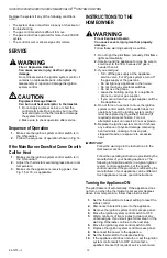
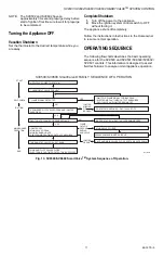
Fig. 14. SV9501/SV9502/SV9602/SV9601 SmartValve
TM
Sequence of Operation.
TROUBLESHOOTING
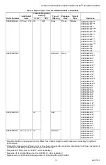
The attached flowcharts provide specific troubleshooting
information for the SV9500, SV9501 and SV9502/
SV9600, SV9601, SV9602 products. These charts assist
the field technician to analyze appliance operation
difficulties.
CAUTION
Equipment Damage.
Can damage connectors on wiring harness.
1.
Proper troubleshooting requires measurement
of voltage and resistance with a volt/ohm meter.
2.
Use proper size probes and appropriate testing
techniques to assure good test information
without damaging the control terminals,
connectors or wiring harness.
Use the following basic troubleshooting procedure.
1.
Review this information carefully prior to going to
the job site.
2.
Identify the specific SmartValve
TM
(SV9500,
SV9501, SV9502, SV9600, SV9601, SV9602).
3.
Make sure the Q3450/Q3480 HSI element is good.
4.
Disconnect the HSI element from the SmartValve
TM
.
5.
Using a multimeter, measure the HSI element room
temperature resistance. It should be less than 10
ohms.
6.
Make sure the SmartValve
TM
switch (knob if
SV9500/SV9600) is in the ON position (unless
directed otherwise in the Troubleshooting
flowchart).
7.
Make sure the appliance call for heat function
provides proper inputs to the SmartValve
TM
through
the 2X2 power connector. (Measure with voltmeter
on the ac scale.)
8.
Follow the Operating Sequence and
Troubleshooting flow charts as shown in Fig. 13 and
15 for the installed SmartValve
TM
SV9500/SV9600
to make sure replacement is necessary.
9.
Follow the Operating Sequence and
Troubleshooting flow chart in Fig. 14 and 16 for the
replacement SV9501/SV9502/SV9601/SV9602
SmartValve
TM
.
NOTE: The HSI element action for SV9501/SV9502/
SV9601/SV9602 is different from the HSI
element action for SV9500/SV9600. For
SV9500/SV9600, the element is on continuously
during a call for heat until shortly after the pilot
flame is detected, the main valve energizes and
the element turns off. For SV9501/SV9502/
SV9601/SV9602, the call for heat generates a
90-second “trial for pilot ignition.” If no pilot flame
is sensed, it retries after a five minute delay. The
element cycles off and back on once during the
trial for pilot ignition.
APPLY 24 VAC TO APPLIANCE
THERMOSTAT CALLS FOR HEAT
PREPURGE (SV9502/SV9602 ONLY)
FLAME SIGNAL DETECTED?
INTERNAL CHECK OKAY?
• PILOT VALVE OPENS
• IGNITER POWERED
PILOT LIGHTS AND FLAME IS SENSED
DURING TRIAL FOR IGNITION?
• IGNITER OFF
• MAIN VALVE OPENS
FLAME SIGNAL LOST?
ELECTRONIC FAN TIMER (EFT) OUTPUT ENERGIZES
THERMOSTAT CALL FOR HEAT ENDS
• MAIN AND PILOT VALVES CLOSE
• EFT OUTPUT DE-ENERGIZES
• MAIN AND PILOT VALVES CLOSE
• EFT OUTPUT DE-ENERGIZES
FIVE-MINUTE
RETRY DELAY
• WAIT FOR FLAME SIGNAL TO DISAPPEAR.
• PILOT VALVE/IGNITER REMAIN OFF
• PILOT VALVE CLOSES
• IGNITER OFF
FLAME LOST MORE THAN FIVE TIMES
IN ONE CALL FOR HEAT?
START
PREPURGE/
SYSTEM
CHECK
TRIAL
FOR
IGNITION
MAIN
BURNER
OPERATION
END
THREE-SECOND FLAME
FAILURE RECYCLE DELAY
NO
NO
NO
NO
NO
YES
YES
YES
YES
YES
M17144A
SV9501/SV9502/SV9601/SV9602 SmartValve® FAMILY SEQUENCE OF OPERATION
IGNITER WILL TURN OFF ABOUT 30 SECONDS INTO THE TRIAL FOR IGNITION IF THE PILOT FLAME HAS NOT LIT. IT WILL TURN BACK
ON FOR THE FINAL 30 SECONDS OF THE 90 SECOND TRIAL FOR IGNITION. THE PILOT VALVE WILL BE ENERGIZED DURING THE
ENTIRE TRIAL FOR IGNITION. THIS IS NORMAL OPERATION FOR THIS GAS IGNITION SYSTEM.
1
1


