


BACNET® FIXED FUNCTION THERMOSTAT
5
31-00093—01
TO SET THE MAC ADDRESS AND DEVICE INSTANCE AT
THE DISPLAY
1.
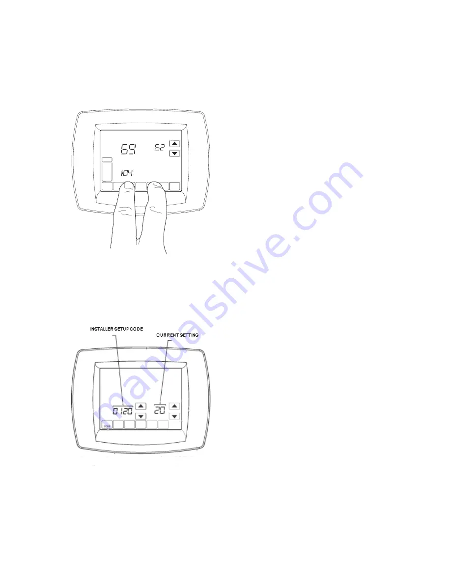
From the home screen, press SYSTEM. Five blank
touch keys will appear at the bottom of the screen.
2.
Press and hold the two blank keys on either side of
the center key for approximately five seconds (see
Fig. 7).
Fig. 7. Entering ISU mode.
The installer setup (ISU) screen appears. An ISU code is
displayed in the lower left. It is a four-digit code beginning
with zero. The current setting is displayed in the lower
right.
Fig. 8. ISU screen.
3.
Use the down arrow next to the installer setup code
to advance to ISU code 800.
4.
Use the up and down arrows next to the current set-
ting to set ISU code 800 (MAC address) to a value
between 0 and 127.
NOTE:
Set ISU code 801 (first digit of device
instance) to a value between 0 and 4.
5.
The device instance is set by entering values in four
separate ISU codes. See example on page 5.
6.
Set ISU code 802 (second and third digits of device
instance) to a value between 00 and 99.
7.
Set ISU code 803 (fourth and fifth digits of device
instance) to a value between 00 and 99.
8.
Set ISU code 804 (sixth and seventh digits of device
instance) to a value between 0 and 99.
9.
Press Done to exit installer setup.
For example, if the MAC address is 15 and the device
instance to 1876, use these settings:
ISU code 800=15
ISU code 801=0
ISU code 802=00
ISU code 803=18
ISU code 804=76
Installer Setup (ISU) Codes
Installer setup mode provides access to functions specific
to installation of a BACnet FF. Some BACnet FF
configuration parameters can be altered from the ISU
screens. The ISU parameters can also be accessed via
BACnet.
A PIN can be required to access ISU mode by setting AV-
133 to a non-zero, four-digit number.
For a complete application configuration guide, refer to
the BACnet Fixed Function Thermostat System
Engineering Guide (31-00098) and WEBs-AX
Configuration Guide (31-00097)
TO ACCESS THE ISU SCREENS
1.
From the home screen, press SYSTEM. Five blank
touch keys will appear at the bottom of the screen.
2.
Press and hold the two blank keys on either side of
the center key for approximately five seconds (see
Fig. 7).
3.
If a PIN code is required, use the top arrows to select
the first two digits of the code and the bottom arrows
to select the third and fourth digits of the code, and
then press DONE.
The ISU screen appears.
4.
Use the arrows to select parameters and values. See
Table 3 for details.
5.
Press DONE.
NOTE:
After five minutes of inactivity, the ISU
screen reverts to the main screen.
DONE
CANC
MO
TU
WE
TH
FR
SA
SU
SYSTE
M
EM
HEAT
OFF
Following
Schedule
Inside
Set To
M19923