Honeywell
Parameter Descriptions
55
10
10. PARAMETER DESCRIPTIONS
On the next pages you can find the descriptions of certain parameters. The descrip-
tions have been arranged according to parameter group and number.
10.1MOTOR SETTINGS (CONTROL PANEL: MENU PAR -> P1)
1.7 C
URRENT
LIMIT
This parameter determines the maximum motor current from the frequency
converter. To avoid motor overload, set this parameter according to the rated
current of the motor. The current limit is equal to the rated converter current
(I
n
) by default.
1.8
M
OTOR
CONTROL
MODE
With this parameter the user can select the motor control mode. The selec-
tions are:
0 = Frequency control:
Drive frequency reference is set to output frequency without slip com-
pensation. Motor actual speed is finally defined by motor load.
1 = Speed control:
Drive frequency reference is set to motor speed reference. The motor
speed remains the same regardless of motor load. Slip is compensat-
ed.
1.9
U/
F
RATIO
SELECTION
There are three selections for this parameter:
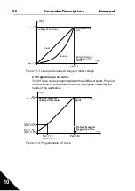
0 = Linear:
The voltage of the motor changes linearly with the frequency in the
constant flux area from 0 Hz to the field weakening point where the
nominal voltage is supplied to the motor. Linear U/f ratio should be
used in constant torque applications. See Figure 10.1.
This default setting should be used if there is no special need for an-
other setting.
1 = Squared:
The voltage of the motor changes following a squared curve form with
the frequency in the area from 0 Hz to the field weakening point where
the nominal voltage is also supplied to the motor. The motor runs un-
der magnetised below the field weakening point and produces less
torque, power losses and electromechaniqal noise. Squared U/f ratio
can be used in applications where torque demand of the load is pro-
portional to the square of the speed, e.g in centrifugal fans and pumps.

