Honeywell PX4ie Скачать руководство пользователя страница 11

10

Applicator Interface Kit Installation Guide

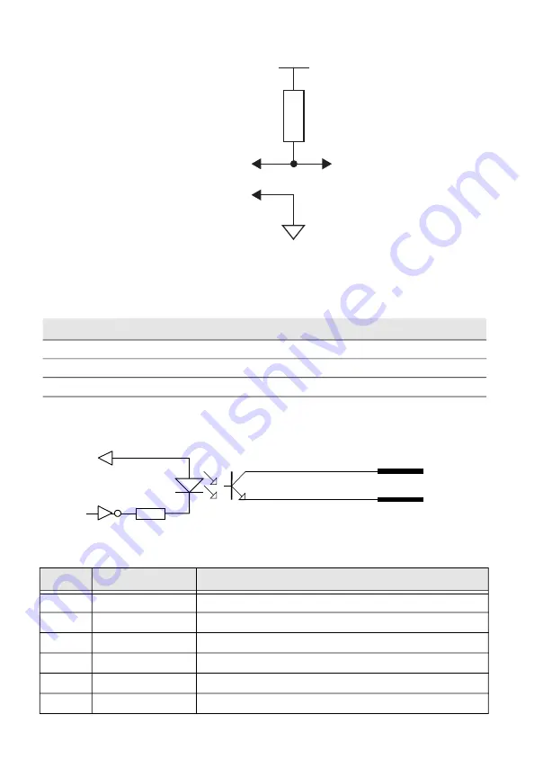
OUT Signals Specification

Simplified schematic of a digital IN port

OUT Signals Connector Configuration

Signal

Description

Max.

Vceo

Collector-Emitter breakdown voltage

35V

Veco

Emitter-Collector breakdown voltage

6V

Ic

Collector Current

15mA

Pin

Signal

Description

20

RibbonLow_C

Ribbon Low Collector Opto Out Channel 

5

RibbonLow_E

Ribbon Low Emitter Opto Out Channel

35

Error_C

Error Collector Opto Out Channel 

21

Error_E

Error Emitter Opto Out Channel

6

EndPrint_C

End Print Collector Opto Out Channel 

36

EndPrint_E

End Print Emitter Opto Out Channel

Collector Pins:

6, 8, 20, 22, 24, 35, 37, 39

Emitter Pins:

5, 7, 9, 21, 23, 25, 36, 38

V+

V-

Output

R

VCC 

OUTc 


OUTa 

Содержание PX4ie

Страница 1: ...Applicator Interface Kit For PX4ie PX6ie Installation Guide PX4 6IE APIBD IG 1 Rev B 07 20 ...

Страница 2: ...nstall the Applicator Interface board in the printer Note This procedure applies to both the PX4ie and PX6ie For simplicity the PX4ie is depicted in the illustrations 1 Turn off the power and disconnect the power cord 2 Disconnect all communication cables 3 Open the right hand door Warning The installation described in this section must only be performed by an authorized service technician Honeywe...

Страница 3: ...ace boards you are going to install Each plate is held by two T10 Torx screws Note Applicator interface card must be installed in the innermost position 7 Save the cover plate s for possible later use Keep the screws Warning The electronics compartment contains high voltage components and wires Do not open the electronics compartment before the printer is safely disconnect from any AC supply Screw...

Страница 4: ...en from behind 12 Installation of one board Attach the interface board in the innermost slot in the printer s rear plate using the two screws left over when you removed the original cover plate Using the T20 Torx screw you previously removed attach the interface board to the hexagonal spacer at the center of the CPU board 13 The kit contains two flat cables one with two connectors for use with a s...

Страница 5: ...ect the power cord and switch on the power 18 In case the interface provides additional serial communication ports enter the Setup Mode to set the proper communication parameters for these ports Remarks The left hand slot is the slot closest to the center section Always start by fitting an interface board in the left hand slot CPU Board Cable Spacer existing Inner Interface Board Screw existing Ap...

Страница 6: ...ts in the socket and are not bent Take ample precautions to protect the board and circuits from electrostatic discharges To configure the board as Install these jumpers and ICs RS 232 1 2 Install a jumper on P3 so that the A is in the middle of the jumper Install IC 360 028 001 MAX238 on SKT3 with pin 1 located where the arrow points to SKT3 toward the bottom of the board RS 422 1 2 Install jumper...

Страница 7: ...XD Receive data 4 DSR Data set ready 5 GND Ground 6 DTR Data terminal ready 7 CTS Clear to send 8 RTS Request to send 9 Not used RS 422 Socket as seen from the outside DB 9 Socket Signal Meaning 1 External 5VDC max 500mA automatic switch off at overload short circuit protected provided strap is fitted on P3 A which spoils the galvanical isolation 2 TXD Transmit data 3 RXD Receive data 4 5 GNDE Gro...

Страница 8: ...he interface board will be displayed on the LCD User interface and the printer web page The applicator interface supports applicator signals with 8 digital IN ports with optocouplers 8 digital Out ports with optocouplers and 4 OUT ports with relays The board has no straps or circuits to be fitted or removed All signals are available on a DB 44 pins socket The Applicator Interface board also provid...

Страница 9: ...tartPrint_K Start print Anode Opto In Channel 40 StartPrint_A Start print Cathode Opto In Channel 26 Feed_A Feed Anode Opto In Channel 11 Feed_K Feed Cathode Opto In Channel 41 Pause_A Pause Anode Opto In Channel 27 Pause_K Pause Cathode Opto In Channel 12 Reprint_A Reprint Anode Opto In Channel 42 Reprint_K Reprint Cathode Opto In Channel 28 AppErr1_A Applicator Error 1 Anode Opto In Channel 13 A...

Страница 10: ... Active Low in accordance with this user guide s logic Assert LOW De assert HIGH Active Low Recommended Output level is V when de asserted Output level is V when asserted Active High Output level is V when asserted Output level is V when de asserted 30 RTWINEXT_K External input signal for Ready to work indicator Anode Opto In Channel 15 RTWINEXT_A External input signal for Ready to work indicator ...

Страница 11: ...own voltage 6V Ic Collector Current 15mA Pin Signal Description 20 RibbonLow_C Ribbon Low Collector Opto Out Channel 5 RibbonLow_E Ribbon Low Emitter Opto Out Channel 35 Error_C Error Collector Opto Out Channel 21 Error_E Error Emitter Opto Out Channel 6 EndPrint_C End Print Collector Opto Out Channel 36 EndPrint_E End Print Emitter Opto Out Channel Collector Pins 6 8 20 22 24 35 37 39 Emitter Pin...

Страница 12: ...Load Breaking Capacity 22 MediaOut_C Media Out Collector Opto Out Channel 7 MediaOut_E Media Out Emitter Opto Out Channel 37 RibbonOut_C Ribbon Out Collector Opto Out Channel 23 RibbonOut_E Ribbon Out Emitter Opto Out Channel 8 DataReady_C Data Ready Collector Opto Out Channel 38 DataReady_E Data Ready Emitter Opto Out Channel 24 VOID_C VOID Collector Opto Out Channel 9 VOID_E VOID Emitter Opto Ou...

Страница 13: ...1com Relay 1 Common 17 REL2nc Relay 2 Normally Closed 2 REL2no Relay 2 Normally Open 32 REL2com Relay 2 Common 18 REL3nc Relay 3 Normally Closed 3 REL3no Relay 3 Normally Open 33 REL3com Relay 3 Common 19 REL4nc Relay 4 Normally Closed 4 REL4no Relay 4Normally Open 34 REL4com Relay 4 Common b inductive load L R 20 ms DC Voltage VDC a resistive load 100 30 40 50 20 0 1 0 1 a b 1 DC Current A 10 ...

Страница 14: ... styles Some port styles may not support all the signals Configuring Applicator Port Settings The applicator interface supports three different applicator modes Z Style Choose this mode for a Zebra type applicator S Style Choose this mode for a Sato type applicator I Style This mode combines Z Style or S Style settings with the ability to trigger external I O systems via the External Error port Yo...

Страница 15: ...Pause Enable this setting to set the Service Required signal when the printer is paused This setting is supported by Z Style only Error Port Enables disables the printer external error port RTW Configures the Ready to Work indicator on the printer front panel Choose from Mode 1 Signal is asserted low when no events are active in the System Health Monitor SHM Mode 2 Signal is asserted low when the ...

Страница 16: ...nd REL4 com respectively Selecting External 24V will switch REL2no and REL4no to REL2com and REL4com respectively Note Users are not restricted to connect DC 24V to these lines Signal Description Startprint Starts a print job Choose either Level or Pulse Level The printer starts printing labels when the startprint signal is asserted and continues printing until the signal is de asserted Pulse The ...

Страница 17: ...the endprint signal may or may not be asserted There are five options to choose from Mode 0 Endprint signal is never asserted Mode 1 Z Style Type 3 S Style Asserted low during print feed cycle Mode 2 Z Style Type 4 S Style Asserted high during print feed cycle Mode 3 Z Style Type1 S Style Asserted lowfor atleast20 ms after print feed cycle end Mode 4 Z Style Type 2 S Style Asserted high for at lea...

Страница 18: ...ealth Monitor SHM RTWOUTEXT External output signal for the Ready to Work indicator Behavior depends on the current setup Signal may be asserted when there are no active events in the System Health Monitor SHM when the printer motor is idle or both This signal is inactive when the Error Port option is disabled SERVICEREQ Service Required Asserted low when an event in the System Health Monitor SHM i...

Страница 19: ...y for the printer These commands are functional when the printer applicator port status is enabled This section includes basic information for each of these commands For more information see the Fingerprint Command reference manual ON PORTIN This command allows a Fingerprint application to detect in signals If a particular in signal is asserted the application moves to the subroutine responsible f...

Страница 20: ... specified subroutine whenever the applicator port status is enabled and whenever the applicator port style is changed Example ON PORTOUT RESET GOSUB nnn Fingerprint and Applicator Signals When you use Fingerprint all in signals and the Dataready out signal are handled by Fingerprint Other out signals are handled by firmware Feed When the Feed in signal is received the application moves to a speci...

Страница 21: ...ETURN Reprint When the Reprint signal is received the application moves to a specified subroutine that reprints the last valid label Example 100 ON PORTIN REPRINT GOSUB 150 150 PRINTFEED 1 1 160 RETURN Printfeed The dataready signal must be set manually by the Fingerprint application before a printfeed is issued when using with an applicator Handling External Applicator Errors When an error signal...

Страница 22: ...s when certain options are changed by using the SETUP menu When the reset is detected the application moves to a specified subroutine and performs the tasks necessary to reinitialize the print engine Example 10 ON PORTOUT RESET GOSUB 150 150 perform initialization 160 RETURN Direct Protocol and Applicator Signals In Direct Protocol all in and out signals are handled by the Direct Protocol firmware...

Страница 23: ... idle when the printer is waiting for a startprint signal during the execution of a printfeed command The printer prints only one label at a time Handling External Applicator Errors The external applicator error in signals APPERR1 APPERR2 APPERR3 RTWINEXT should be asserted when external applicator errors occur When one of these signals is detected an associated event is activated in the System He...

Страница 24: ...FF on a port used by the applicator port when the applicator is enabled Error number 89 ERRINPUTON Message Operation not allowed in Direct Protocol Cause Running the PORTOUT DATAREADY ON OFF or PORTIN SIGNAL GOSUB XXX commands when the printer is set to using Direct Protocol Error number 90 EAPPERR1 Message Applicator Error 1 Cause AppErr1 in signal detected Result Activates event in System Health...

Страница 25: ... Dataready not enabled Cause Application sent a PRINTFEED in Fingerprint when the applicator port is enabled the style is set to I Style or Z Style and the dataready signal is not enabled Result Terminates the printfeed command without printing a label Error number 1344 Message APPLICATOR PORT Wait for signal Cause Running a PRINTFEED command blocks execution until a startprint signal is received ...

Страница 26: ...tor interface ports are detailed below DB 44 Connector Pin Applicator Interface 44 pin External Error Port 8 pin Pin Type Pin Signal Type Description 28 Input 1 AppErr_1 Input Applicator error 1 13 43 Input 2 AppErr_2 Input Applicator error 2 29 14 Input 3 AppErr_3 Input Applicator error 3 44 30 Input 4 AppErr_4 Input Honeywell Ready to Work indicator input for external errors RtW_In_Ext 15 39 Out...

Страница 27: ...Input 40 26 Input 4 Feed Input 11 41 Input 5 Pause Input 27 12 Input 6 Reprint Input 7 Reprint Input 42 20 Output 9 Ribbon Low Output 10 Ribbon Low Output 5 35 Output 10 Service Required Output 4 Error Output 21 6 Output 11 End Print Output 6 End Print Output 36 22 Output 12 Media Out Output 1 Media Out Output 7 37 Output 13 Ribbon Out Output 3 Ribbon Out Output 23 8 Output 14 Data Ready Output 38...

Страница 28: ... the reader should in all cases consult HII to determine whether any such changes have been made The information in this publication does not represent a commitment on the part of HII HII shall not be liable for technical or editorial errors or omissions contained herein nor for incidental or consequential damages resulting from the furnishing performance or use of this material HII disclaims all ...

Отзывы: