background image

8

7

D

C

 5

V

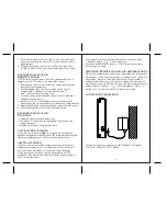
BATTERY INSTALLATION 

MAIN UNIT

1. Open the battery compartment door.

2. Install two AA batteries (not included) matching to the

polarities shown.

3. Replace the battery compartment door.

LOW BATTERY WARNING

A low-battery indicator [       ] will appear on the indoor or

outdoor temperature reading line of the main unit warning that

the corresponding sensor’s batteries need replacement.

GETTING STARTED

After batteries are installed, remote sensors will transmit a

temperature readings at 45 second intervals. The main unit

may take up to 2 minutes to receive the initial readings.

Upon successful reception, remote temperature will be

displayed. The main unit will automatically update readings

at 45-second intervals.

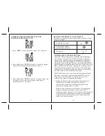
CHECKING REMOTE AND INDOOR TEMPERATURES

The indoor temperature is shown on the middle line of the main

unit display. The remote temperature is shown on the top line of

the display. The wave icon near the remote sensor reading

indicates that there is a good signal reception from the remote

unit. If there is no signal received from the remote unit for more

than 2 minutes, a dashes “        ” will be displayed. Hold [ – ]

button for 2 seconds to enforce an immediate search.

If no signals are received from the remote sensor(s) within

2 minutes, dashes “       ” will be displayed.

Press and hold DOWN button [ – ] for 2 seconds to activate

another signal search.

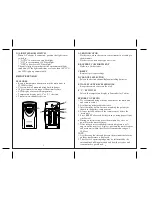
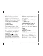
BATTERY INSTALLATION

REMOTE SENSOR

NOTE: Install the batteries; select the channel and type of

temperature (ºC/ºF) before you mount the sensor.

1. Remove the screws from the battery compartment with a

small Phillips screwdriver.

2. Set the channel. The switch is located in the battery

compartment.  Channel 1 is typically selected if

only 1 remote sensor is being used.

3. If you are using more than one sensor, select a different

channel for each sensor.

4. Install two “AA” size alkaline batteries (not included)

matching to the polarities shown in the battery compartment.

5. Replace the battery compartment door and secure the screws.

6. Secure the remote sensor in the desired location.

3. Position the remote sensor so that is faces the main unit

(receiver), minimizing obstructions such as doors, walls,

and furniture.

4. Though the remote sensors are weather-resistant, they

should be placed away from direct sunlight, rain or snow.

CONTINUOUS PROJECTION

Insert 2 AA batteries and connect the included AC adapter

(AC120V, 60Hz-DC5.0V, 100mA).

Содержание PCR325W

Страница 1: ...1 1 Wireless Weather Projection Clock with Light Detector USER MANUAL PCR325W ...

Страница 2: ...display Multi channel capability to monitor temperature in up to three remote locations additional sensors required Outdoor temperature Barometric pressure with three trend indicators Rising Steady Falling Weather forecast in five large graphic icons Sunny Partly Cloudy Cloudy Light Rain and Heavy Rain Current time and remote temperature projected onto the wall or ceiling in bright red digits Prec...

Страница 3: ...three different alarm modes Sets the weekday alarm single alarm or pre alarm D MODE BUTTON Toggles between the clock modes the time with the seconds and the time with the day of week Sets the clock manually E LIGHT SNOOZE BUTTON Activates the snooze feature backlight and projection F DOWN BUTTON Decreases the setting G UP BUTTON Increases the setting H BATTERY COMPARTMENT Holds two AA batteries I ...

Страница 4: ... remote temperature will appear on the receiver s display position the remote sensor and main unit within the effective transmission range of 100 feet NOTE 1 Avoid setting the time and date on the main unit before the outdoor temperature is displayed 2 The effective operating range may be influenced by the surrounding building materials and how the receiver and transmitter are positioned A LED IND...

Страница 5: ...inutes a dashes will be displayed Hold button for 2 seconds to enforce an immediate search If no signals are received from the remote sensor s within 2 minutes dashes will be displayed Press and hold DOWN button for 2 seconds to activate another signal search BATTERY INSTALLATION REMOTE SENSOR NOTE Install the batteries select the channel and type of temperature ºC ºF before you mount the sensor 1...

Страница 6: ... miles away Due to the nature of the Earth s ionosphere reception can be limited during the daylight hours The radio controlled clock will search for an alternate station that derives its signal from the NIST Atomic clock in Boulder Colorado The WWVB tower icon on the main unit s display will flash indicating radio signal reception from the WWVB station If the tower icon is not fully lit or if the...

Страница 7: ... Use lithium ion batteries at the temperatures below 32 F NOTE 1 The weather forecast accuracy is approximately 70 2 Display shows forecasted not current conditions 3 The Sunny icon indicates clear weather even when displayed during nighttime hours BAROMETRIC PRESSURE The barometric pressure arrows indicate if pressure is rising steady or falling INDOOR ANR OUTDOOR TEMPERATURES The trend indicator...

Страница 8: ...inutes the time signal has not been received press the MODE button to set the time manually The clock will continue to search for the WWVB time signal daily from 1 00 am to 4 30 am When the signal has been successfully received the time and date will be updated automatically MANUAL SETTINGS TIME ZONE 1 Press MODE to select the time with the day of week display mode 2 Select the time zone by pressi...

Страница 9: ...e warranty and may cause damage These units contain no user serviceable parts 5 Use only fresh batteries Do not mix new and old batteries 6 Read the user s manual thoroughly before operating the units SETTING THE ALARM To set any alarm 1 Press ALARM ON OFF once to display a specific alarm time If the selected alarm is off OFF will be displayed 2 Press and hold ALARM ON OFF for 2 seconds The hour d...

Страница 10: ...o the following two conditions 1 This device may not cause harmful interference and 2 This device must accept any interference received including interference that may cause undesired operation Warning Changes or modification to this unit not expressly approved by the party responsible for compliance could void the user s authority to operate the equipment NOTE This equipment had been tested and f...

Страница 11: ...over damages or wear resulting from accident misuse abuse commercial use or unauthorized adjustment and repair Note that online product registration is required to ensure valid warranty protection To register your product go to our Company website at www hidekielectronics us Click Online Product Registration under the Customer Service menu Should you require assistance with this product and its op...

Отзывы: