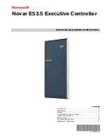
NOVAR ES3.S EXECUTIVE CONTROLLER
31-00366—01
6
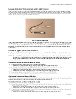
• Board without UL Label: Terminal #58 (-) at the Outdoor Light Sensor Input connections
3.
Verify that the Outdoor Light Sensor current mode switch is in the disabled (off) position.
Outdoor Temperature Sensor
The Novar
standard
OTS is not supported by the Novar ES3.S; therefore, installation of the Novar 4-20 mA Outdoor
Temperature Sensor (OTS/2) with xcm.10S or Savvy retrofits will be required. Refer to the steps below for installation.
1.
Connect the white (+) wire from the sensor to the transition board at Terminal #62 (+) at the Outdoor Temperature
Sensor Input connections.
2.
Connect the black (-) wire from the sensor to the transition board at Terminal #60 (-) at the Outdoor Temperature
Sensor Input connections.
3.
Connect the shield wire from the sensor to the transition board at Terminal #61 (Shield).
4.
Verify that the Outdoor Temperature Sensor current mode switch is the enabled (on) position.
Optional Universal Input Wiring
If the Outdoor Temperature Sensor input is to be used in the optional Universal Input configuration mode, the input
wiring will be different than that used in current mode. Refer to the steps below for proper wiring.
1.
Connect the signal wire (+) from a 0-10V source or, one terminal of a thermistor, resistive or dry contact digital type
input to the transition board at Terminal #60 (-) at the Outdoor Temperature Sensor Input connections.
2.
Connect the return or ground wire (-) from a 0-10V source or, one terminal of a thermistor, resistive or dry contact
digital type input to the transition board at Terminal #61 (Shield) at the Outdoor Temperature Sensor Input connec-
tions.
3.
Verify that the Outdoor Temperature Sensor current mode switch is the enabled (on) position.
RS485 Communications Networks
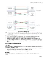
Legacy modules use a different RS-485 polarity standard than Opus or generic "open" controllers, which follow the EIA-
RS-485 standard. Refer to Table 1 and Fig. 5 to determine the correct standard used on the various Novar ES3.S network
interfaces.
There are not LEDs showing the transmit/ receive status of COM Port 2. The RS485 COM Port is labeled MODULE
NETWORK on the transition board of the Savvy Base (Terminals 39, 40, 41).
The RS485 COM Port is labeled NETWORK "D" on the transition board of the Savvy Base (Terminals 71, 72, 73).
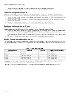
Table 1. Communications Table.
Network Name
Location
COM- #
Wiring Polarity Standard
Module Network
Baseplate
2
Novar Legacy
Network D
Baseplate
4
Novar Legacy
COM-3
Expansion Interface
3
Opus/EIA RS-485
COM-5
Expansion Interface
5
Opus/EIA RS-485
COM-6
Expansion Interface
6
Opus/EIA RS-485

