IDR-M Mimic Installation & Commissioning Manual
Installation Guide
11
997-412-000-3, Issue 3
June 2005
2.5
Installation Procedure
2.5.1 IDR-M Control Board Kit
2.5.1.1 Termination Board Connections
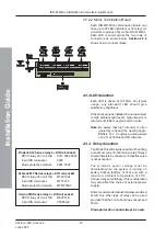
The following connections are required:
a. 28V (18-32V) dc and 0V supply, from
previous mimic, or from panel, or from
external source.
Note:
The Fire Control panel auxiliary outputs
must not be used if the current
requirement of the mimic(s) is >0.5A.
b. 28V (18-32V) and 0V output to next mimic.
c. Power Fail (PF) input. This is not used by
the IDR-M.
d. RS485 serial data link (A and B) from the
previous station in the network (where
‘station’ is a fire control panel, repeater or
mimic).
e. RS485 serial data link (A and B) to the next
station in the network.
f. RS232 ribbon cable [used in place of (d)
and (e) above when IDR-M is connected to
ID
2
net via a Network Gateway Unit (NGU)].
Connection to the NGU is made via two
Isolated RS232 Boards (see below left).
The ribbon cable is supplied with the
Isolated RS232 Board.
The ribbon cable connection to/from the Mimic
Control board is already provided.
For ease of wiring, all connections are
identified in the silk screen on the PCB.
a
d
e
b
c
f
RIBBON
RIBBON
RS232 LINK
ISOLATED
RS232 PCB
ISOLATED
RS232 PCB
TERMINATION
PCB
PSU
INTERFACE
PCB
NGU - SEE 997-451
FOR DETAILED
WIRING INFORMATION
NGM
DC POWER CONNECTION
NGU TO IDR-M MIMIC INTERCONNECTIONS
IDR-M MIMIC


