IDR-M Mimic Installation & Commissioning Manual
Installation Guide
15
997-412-000-3, Issue 3
June 2005
Jumper Links
The 64 output channels are arranged in two
banks of 32. Each bank is arranged in four
groups of eight outputs. Each group is provided
with a jumper link which configures the group
to drive either LEDs or relays:
Jumper FITTED = group drives RELAYS.
Jumper NOT FITTED = group drives LEDs.
The groups can be configured independently, i.e.
within a bank some groups may drive relays and
others may drive LEDs.
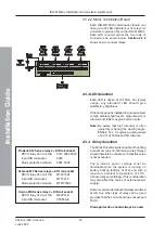
The illustration at left identifies jumpers to groups
of eight output channels.
CAUTION: Ensure that jumper links are
configured correctly. If an LED is
connected to an output for which
the link is fitted, the LED will have
a short life expectancy.
Conversely, if a relay is connected
to an output for which the link is
not fitted, the relay will not operate.
Digital I/O - Inputs
The IDR-M Mimic Driver board is provided with
eight pre-configured digital inputs as defined
below; this is only applicable to an IDR-M
Mimic Driver board when used singularly, or if
it is the first of two or more ‘daisy-chained’ boards.
Digital I/O - Outputs
If the IDR Configuration Tool is used to
configure the IDR-M mimic, the digital inputs
can be re-configured as relay outputs as shown
below and at left. These outputs can be enabled
or disabled by S1-2 (see table on previous page).
CONNECTOR J6 - WIRED FOR INPUTS
CONNECTOR J6 - WIRED FOR RELAY OUTPUTS (connect
other side of relay coils to 28V)
0V for inputs and
28V for outputs are
available at J5


