background image

ML6174, ML7174 NON-SPRING RETURN DIRECT COUPLED ACTUATORS

63-2534—1

4

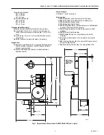
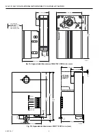
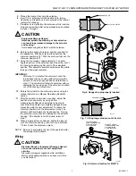
Fig. 1A. Approximate dimensions of ML6174C,D DCA in in. (mm).

M11621

60

°

45

°

45

°

60

°

5-7/8
(149)

1-13/16

(46)

1

(25)

3-5/8  (92)

1-13/16  (46)

3 IN. (76 MM)
MINIMUM SPACING
REQUIRED 
FOR REMOVING 
CONDUIT COVER

3-3/4  (95)

7/8
(22)

1

(25)

M10244A

OPTIONAL
AUXILIARY
SWITCH

T1

T2

-

+
+

24 Vac

2-10 Vdc

4-20 mA

4-7/8
(123)

4-1/4
(108)

5-9/16

(141)

11/16

(18)

1/8

(3)

3-3/8  (86)

1/8 (3)

15/32

(12)

2-7/8  (73)

1-11/16 (42)

1/8

(3)

3 (76)

5/32

(9)

7/8

(22)

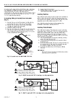
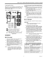
Fig. 1B. Approximate dimensions of ML7174 DCA in in. (mm).

Содержание ML6174 Series

Страница 1: ...90 second timing models suitable for use with pressure independent VAV systems Seven minute timing models suitable for use with pressure dependent VAV systems Magnetic coupling provides 130 lb in or less stall torque eliminating the need for mechanical stops or limit switch adjustments Two field addable auxiliary switches Auxiliary feedback potentiometer field addable on some models 0 to 30 minimu...

Страница 2: ...ter drive for use with field addable feedback potentiometer minimum position adjustment setscrews for cw or ccw operation 4074ENJ Bag Assembly and integral conduit cover ML6174D 90 second 7 minute timing spdt Floating Series 60 Available with minimum position adjustment setscrews Includes 4074ENJ or 4074ENY Bag Assembly as appropriate and integral conduit cover ML7174A 90 second timing 2 to 10 Vdc...

Страница 3: ...se Output 45 dBA at 1 meter maximum Accessories 200976A Auxiliary Potentiometer 0 to 500 ohm 200976C Auxiliary Potentiometer 0 to 2000 ohm 201052A Auxiliary Switch one 201052B Auxiliary Switch two 4074ENJ Bag Assembly includes stop pin shaft adapter and two minimum position screws 4074ENY Bag Assembly includes stop pin and shaft adapter 4074EVK Short Shaft Extender 7640QW Metal Enclosure for attac...

Страница 4: ...9 1 13 16 46 1 25 3 5 8 92 1 13 16 46 3 IN 76 MM MINIMUM SPACING REQUIRED FOR REMOVING CONDUIT COVER 3 3 4 95 7 8 22 1 25 M10244A OPTIONAL AUXILIARY SWITCH T1 T2 24 Vac 2 10 Vdc 4 20 mA 4 7 8 123 4 1 4 108 5 9 16 141 11 16 18 1 8 3 3 3 8 86 1 8 3 15 32 12 2 7 8 73 1 11 16 42 1 8 3 3 76 5 32 9 7 8 22 Fig 1B Approximate dimensions of ML7174 DCA in in mm ...

Страница 5: ...ise direction The actuator has a mounting tab on the bottom that secures it to a damper box When mounted correctly this tab allows the actuator to float without rotating relative to the damper shaft The tab is sized for 1 4 in 6 mm self tapping sheet metal screws not provided CAUTION Equipment Damage Hazard Tightly securing mounting tab to damper housing can damage actuator Do not fully tighten th...

Страница 6: ...tuator Do not fully tighten the screw when mounting to allow the actuator to float 5 Position the damper in the open position and tighten the Allen screws securely into the damper shaft 6 If the angle of the damper opening is 45 close the actuator using the manual declutch a Disengage the hub using the declutch lever see Manual Operation Declutch section b Rotate the hub until the actuator gear tr...

Страница 7: ...housing only if the setscrew is backed out of the housing turned ccw 10 Rotate the actuator to the minimum position using the manual declutch see Manual Operation Declutch section 11 After the actuator is at minimum position adjust the position more accurately by using air flow measurements After each adjustment be sure to check that the actuator is completely stopped before proceeding with the ne...

Страница 8: ... the actuator for example electric reheat coils and fan at an adjustable point in the actuator stroke 0 to 90 The 201052 Auxiliary Switches are field addable For installation instructions see form 63 2218 Auxiliary Potentiometers The 200976A C Auxiliary Potentiometers mount on the face of the ML6174A C as shown in Fig 12 The potentiometer shaft has a slipping collar If one of the two limits of the...

Страница 9: ...essure controller regulates the total air flow in the system The fan system is sized to handle an average peak load not the sum of the individual peaks As each zone peaks at a different time of day extra air is borrowed from the off peak zones This transfer of air from low load to high load zones occurs only in true VAV systems In pressure independent systems individual zone airflow sensors mainta...

Страница 10: ... PHASE SHIFT CAP DRIVE CCW WINDING DRIVE CW WINDING COM COMMON AS SHOWN T641 MAKES R Y CONTACTS TO DRIVE ML6174 ACTUATOR CCW AND MAKES R W CONTACTS TO DRIVE ML6174 ACTUATOR CW M12574 ML6174 ACTUATOR Fig 14 T641A C controlling ML6174 ML7174 Actuators Voltage input 2 to 10 Vdc Wire the Vdc and terminals of each actuator in parallel Make certain the total connected load does not exceed the current ca...

Страница 11: ...amper is closed it should begin to open 3 If not adjust the setpoint of the thermostat higher to determine if the wiring is correct 4 If no movement is observed check for the presence of 24 volts 5 If using the T641 Thermostat the 24 volts should be present between terminals C and Y during a call for cooling With proper wiring and 24 volts present the actuator should operate correctly If not repla...

Страница 12: ...re No 30 Harbour Road Wanchai Hong Kong Home and Building Control Honeywell Limited Honeywell Limitée 155 Gordon Baker Road North York Ontario M2H 3N7 Honeywell Latin American Region 480 Sawgrass Corporate Parkway Suite 200 Sunrise FL 33325 63 2534 1 B B Rev 12 97 Printed in U S A Home and Building Control Honeywell Inc Honeywell Plaza P O Box 524 Minneapolis MN 55408 0524 www honeywell com ...

Отзывы: