


LYNX Touch Installation and Setup Guide
- 6 -
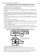
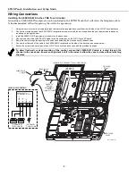
Mounting the Control
Wall Mounting
5100-100-064-V0
LOCKING
TABS
TIE WRAP
POINTS (2)
FRONT
CASE
BACK
CASE
INSTALL
SCREW
IN CASE
TAMPER
MOUNTING
HOLES (4)
ROTATE
FRONT CASE
UPWARD
TO RELEASE
HOOKS
TIE WRAP
POINT (3)
MOUNTING
HOOKS (HINGES)
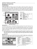
Release the front case from the back case by
depressing the two locking tabs at the top of the unit
with the blade of a medium size screwdriver.
Separate the front and back case assemblies by rotating
the front case so that it is perpendicular to the back
case and unsnapping (releasing) the two hooks from the
back case.
Feed the field wiring through the appropriate openings
in the back case. Use tie-wraps to secure the wiring to
the built-in wire loops as needed.
DETAIL A
Mount the back case to a sturdy wall using self tapping screws.
If required, install an additional mounting screw in the case
tamper (see Detail A).
Attach the front and back cases by connecting the
hooks on the front case to the attachments on the back
case. Once attached, the hooks will support the front
case and allow you to make the wiring connections.
After all wiring connections have been made, snap the
front case and back case closed and ensure that the case
is secured by the locking tabs.
1.
2.
3.
4.
5.
6.
7.
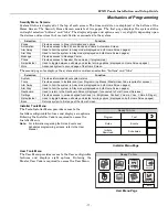
Desktop Mounting
For desktop mounting, the optional mounting base (model L5000DM, purchased separately) must be used.
5100-500-004-V0
Slide the control panel onto the mounting base locking
tabs.
Bring all wiring through the bottom of the mounting
base, using one of the wire entry locations, before
making connections to the control panel.
Use tie-wraps to secure the wiring to the built-in wire
loops as needed.
Use the supplied screws to secure the control panel to
the mounting base.
1.
2.
3.
4.
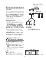
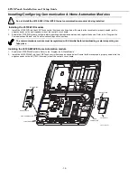
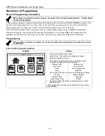
Wiring Overview
The following summarizes the connections required. Refer to the Wiring Connections paragraph and the
Summary of Connections diagram on the inside back cover when making connections.
5100-100-062-V0
TERMINAL
STRIP
TELEPHONE
CONNECTION
TELEPHONE
CONNECTIONS
POWER SUPPLY
RECEPTACLE
STANDARD
CAPACITY BATTERY
CONNECTION
SUPER
HIGH CAPACITY
BATTERY
CONNECTION
EDGE
CONNECTOR
TAMPER
SWITCH
GSMVLP5-4G/ILP5
RECEPTACLE
EDGE
CONNECTOR


