Honeywell IQ Force Скачать руководство пользователя страница 24

IQ Force™ Dock Reference Manual

16

Connecting the Calibration Gas Cylinder to the Dock(s)

2.7.3.2.3 Multi-Dock Setups with Fresh Air Manifold

For more information on this, see Applications Note # AN20050722, which 

is available at http://www.honeywellanalytics.com.
The manifold is necessary for use when more than one dock is to be used 

with an external fresh air source, whether is be a cylinder of “zero air” or a 

sealed conduit to a fresh air source. 
The manifold is composed of:

•  (3) small black T-fittings

• 

(4) clear one-way check valves

•  (10) pieces of gas tubing 5″ long
•  (1) piece of gas tubing 10″ long

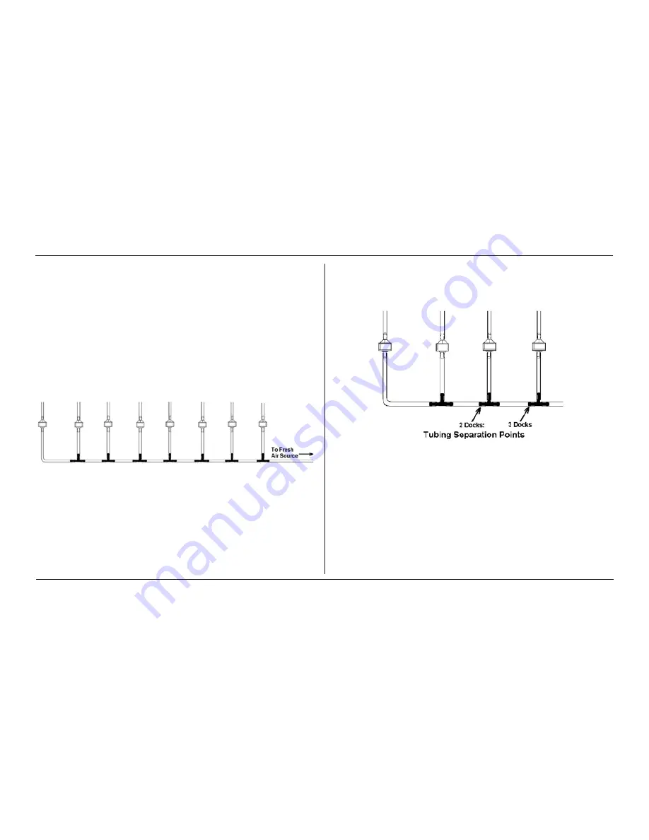
Figure 9. 54-46-115 Tubing Assembly

1. 

If the fresh air source is a calibration gas cylinder, insert the Demand 

Flow Regulator into the calibration gas cylinder and proceed to 

step 2.
OR

If the fresh air source is a sealed conduit from an external fresh 

air source, install the fresh filter on each dock as described above 

and proceed to step 2.

2. 

Modify the tubing assembly as follows depending on how many 

docks will be connected. If four docks will be used, no modifications 

are necessary. For two or three docks, begin by separating the tubing 

at the location described below.

Figure 10. Tubing Separation Points

Содержание IQ Force

Страница 1: ...IQ Force Dock Reference Manual ...

Страница 2: ......

Страница 3: ...storage installation calibration use maintenance and compliance with the product manual instructions and any other applicable recommendations of HA b the buyer promptly notifying HA of any defect and if required promptly making the product available for correction No goods shall be returned to HA until receipt by the buyer of shipping instructions from HA and c the right of HA to require that the ...

Страница 4: ...Caribbean Honeywell Analytics Av MarginaldaRodoviadosBandeirantes 100 Distrito Industrial Jundiaí São Paulo Brasil ZIP 13213 008 Tel 55 11 3309 1030 Fax 55 11 3309 1005 hala honeywell com Europe Middle East and Africa Life Safety Distribution AG Wilstrasse 11 U11 CH 8610 Uster Switzerland Tel 41 0 1 943 4300 Fax 41 0 1 943 4398 gasdetection honeywell com Asia Pacific Honeywell Analytics Asia Pacif...

Страница 5: ...sktop Software Installation 4 2 5 Install IQ Administrator Pro Database Manager and Post greSQL database 9 2 6 Power and Connectivity 9 2 6 1 PC Single Dock via USB 9 2 6 2 PC Multi Dock via USB 9 2 7 Connecting the Calibration Gas Cylinder to the Dock s 10 2 7 1 Single Cylinder to Single Dock 11 2 7 2 Single Cylinder to Multiple Docks 11 2 7 3 Fresh Air Port Instructions 14 2 8 Initial PC Dock Co...

Страница 6: ...t 36 4 2 2 Outright Failure to Connect 37 4 3 Test Failures 37 4 3 1 No gas detected 37 4 3 2 Span calibration failure 38 4 3 3 Alarm test failure 38 4 3 4 PC Aborted Test 38 5 Menu Items 38 5 1 File Menu 38 5 2 Tools Menu 39 5 2 1 Dock 39 5 2 2 IQ Force 40 5 2 3 Certificates 41 5 2 4 Email 42 5 3 Help Menu 42 5 3 1 Check for Update 42 5 3 2 About IQ Force 43 6 Software Upgrades 44 Appendix A Cali...

Страница 7: ...he user is properly warned of potentially dangerous atmospheric conditions it is essential that the instructions in this manual and the operations and or reference manual s for the gas detector s be read fully understood and followed This manual is not intended to replace the operations and or reference manuals for the gas detector This manual is designed only to aid in the installation and operat...

Страница 8: ...ided will result in death or serious injury WARNINGindicates a potentially hazardous situation which if not avoided could result in death or serious injury CAUTION indicates a potentially hazardous situation which if not avoided may result in moderate or minor injury CAUTION used without the safety alert symbol indicates a potentially hazardous situation which if not avoided may result in property...

Страница 9: ... is to be used as a stand alone calibration station with non standard alarm settings the dock must be reprogrammed with the IQ Force dock software The IQ Force dock software must be loaded onto the PC prior to completing the USB connection NOTE Do not connect the IQ Force dock to the PC until the software has been installed 1 1 Tests and record keeping The IQ Force dock performs the following proc...

Страница 10: ...t have additional controls at the PC to ping the dock and to view the ethernet settings 1 3 PC Requirements Pentium Processor 1 0GHz or better or equivalent 512MB RAM XP Vista Server 2003 Windows 7 32 and 64 bit 50MB hard drive disk space 1 4 Power Requirements The IQ Force dock is delivered with an appropriate power supply and a variety of adapters The IQ Force dock must be plugged into an approp...

Страница 11: ...he time of purchase all IQ Force docks are shipped from Honeywell Analytics configured with the standard calibration gas settings which are shown in Section 1 6 Whenever the user chooses to activate the IQ Force without an active PC connection the dock will operate with the last set of calibration gas settings that were uploaded into the instrument Note Do not connect the IQ Force dock to the PC u...

Страница 12: ...Q Force installation CD Place the CD in your PC s CD tray and follow the installation instructions given in the IQ Administrator Pro and Postgre SQL Reference Manual that is included with the dock 2 3 IQ Database Manager Software Installa tion The Database Manager Pro Program is contained on the IQ Force Installation Disc Place the disc in your PC s CD tray and follow the installation instructions...

Страница 13: ...ual 5 IQ Force Dock Desktop Software Installation 2 Select IQ Force and click Install The InstallShield Wizard will begin the installation 3 Click Next to continue with the installation The LicensingAgreement screen will be shown ...

Страница 14: ...top Software Installation 4 If you accept the terms of the License Agreement click I accept and then click Next to continue The upgrade information and PC requirements will be shown 5 Click Next to continue The Customer Information screen will be shown ...

Страница 15: ...yone who uses this computer or Only for me Then click Next The destination folder screen will be shown 7 To install the software in the default directory at C Program Files Biosytems IQ Pro IQ Force click Next To install the files to another directory click Browse and use Windows Explorer to specify the new location Click Next once this is accomplished The following screen will then be shown ...

Страница 16: ...ftware Installation 8 Click Next to continue The status of the file decompression will be shown Once the installation is complete the following screen will be shown 9 Click Finish to conclude the installation The IQ Force dock logo will appear on your desktop ...

Страница 17: ...s USB port IQ Force docks that are Ethernet ready are shipped with an Ethernet Instruction booklet Proceed to the Ethernet Instruction booklet if you are planning to connect the dock to the PC via Ethernet Once the instructions in the booklet have been followed and the IQ Force dock is connected return to Section 2 7 for calibration gas cylinder connection instructions 2 6 1 PC Single Dock via USB...

Страница 18: ...available If you have enough open USB ports on your PC to connect each of the docks directly to its own USB Port you may connect each dock directly to the PC Most users decide against this option either because their PC doesn t have enough USB ports or because it is an inappropriate use of their PC s system resources CAUTION Under no circumstances can multiple IQ Force docks be run from a single U...

Страница 19: ...S port on the dock see Figure 2 Figure 1 4 Proceed to Section 2 7 3 for further instructions concerning the fresh AIR port 2 7 2 Single Cylinder to Multiple Docks When multiple IQ docks are connected to a single cylinder of calibration gas a manifold is used to disperse the calibra tion gas from the cylinder to the docks The manifold is a HoneywellAnalytics part and includes a detailed instruction...

Страница 20: ...he 54 46 115 manifold is composed of 1 small black elbow fitting 3 small black T fittings 2 pieces of gas tubing 5 long 1 piece of gas tubing 10 long 1 piece of gas tubing 1 long Figure 2 1 Insert the demand flow regulator into the calibration gas cylinder 2 Modify the tubing assembly as follows depending on how many docks will be connected If four docks will be used no modifications are necessary...

Страница 21: ...k Connect the white quick disconnect fittings to the GAS ports on the docks and connect the open ends to the manifold s open T fittings At this point tubing should run from each dock s GAS port to the T fittings There should be no open T fittings in the procedure but there should be one piece of open tubing on the elbow fitting 4 Connect the open piece of tubing on the elbow fitting to the Demand ...

Страница 22: ...ore than one dock is used 2 7 3 1 Fresh Air Filter Under normal circumstances the IQ Force dock is located in a fresh air environment and fresh air is drawn in from the local environment A filter is included with the dock that is used to protect the dock from contaminants that may inadvertently enter the dock The air filter should be installed if the dock is drawing fresh air from the immediate su...

Страница 23: ...as tubing For single docks simply connect the zero air cylinder and demand flow regulator to the dock s AIR port using standard gas tubing A check valve is not necessary when a cylinder is used to provide fresh air to a single dock The fresh air filter is also not required in this configuration For multiple dock setups up to four a one way check valve must be placed in the line between each T fitt...

Страница 24: ... 4 clear one way check valves 10 pieces of gas tubing 5 long 1 piece of gas tubing 10 long Figure 9 54 46 115 Tubing Assembly 1 If the fresh air source is a calibration gas cylinder insert the Demand Flow Regulator into the calibration gas cylinder and proceed to step 2 OR If the fresh air source is a sealed conduit from an external fresh air source install the fresh filter on each dock as describ...

Страница 25: ... above the check valves to filter that was installed on the dock in step 2 At this point the tubing assembly should be connected to each dock s AIR port 4 Connect the only open piece of tubing below the black T fittings to the demand flow regulator on the gas cylinder or to the conduit for the external source of fresh air 2 8 Initial PC Dock Connection Once the software has been installed and the ...

Страница 26: ...ock is plugged into a USB Port that was most recently used for a different device NOTE These screens will vary depending on your PC s operating system 1 The software will prompt to ask if it should connect to Windows Update to search for software Make a selection based on how you would like to use your PC s operating system and click Next to continue The Wizard will proceed to search for the USB d...

Страница 27: ...ection 2 Select Install the software automatically and click Next 3 In Windows XP a warning may appear screen will be shown stating that IQ Force software has not passed Windows Logo testing Click Continue Anyway XP Only The installation will then continue ...

Страница 28: ...k firmware version and serial number are displayed IQ Force Dock Version 7 62 IQ Force Dock Serial 100200302 If an alias is set for the dock in the IQ Force Desktop software see Section 3 1 1 this screen is then displayed IQ Force Dock OFFICE 1 NOTE The dock LCD can display upper and lower case letters and numbers If other characters are used in the dock alias they may not display properly ...

Страница 29: ... Interval 30 days If the USB cable is not connected to the dock the following three screens are displayed Checking Network Module Configuring Network Module IP Address Is 151 150 10 201 When the dock is ready to accept an instrument it alternates between the following two screens READY 10 25 20 APR 2012 READY 10 25 CO H2S LEL NOTE The asterisk to the right of the time indicates that the dock is co...

Страница 30: ...ecting Programs Honeywell IQ Pro IQ Force IQ Force unless another location was specified during the installation The following screen will be shown once the application is launched The screen is divided into right and left sides The left side gives the status of the docks that are currently installed and recognized At the top of the right side of the screen there is a tab for each dock that is cur...

Страница 31: ... the dock the green Detected indicator will light to reflect the new status Status changes are also be shown on the dock s LCD During processing the yellow Processing indicator LED will come on The dock operations performed on the instrument are listed as they occur If the dock is able to successfully complete the processing dictated by the instrument s template in the IQ Database Manager Pro Prog...

Страница 32: ...under the instrument tab See Section 3 1 2 for details on faults 3 1 Dock Controls and Instrument Status The right side of the screen contains individual controls for each IQ Force dock Each dock has its own page which can be accessed by clicking on the appropriate tab at the top of the page Within each dock s page are two sub tabs One contains specific information on the dock itself The other dis...

Страница 33: ...ctor Non matching calibration gas and calibra tion gas value settings will lead to inaccurate and potentially dangerous readings 3 1 2 Hardware Configuration The hardware configuration section contains the serial number and software version number of the dock at the upper left corner This information may not be changed with the software Software updates can cause the dock firmware version to chang...

Страница 34: ...to be to pass the test The sound level is given in decibels when the cursor is placed over the slider The minimum sound level that will be accepted by the software is 80 dBA 3 1 5 AC Power The AC Power indicator is located directly beneath the connection speed setting If the dock is being powered by the USB cable the AC Power will appear grey When the dock is being powered by an AC power source th...

Страница 35: ...for repair 3 1 9 Calibration Interval The dock s calibration interval settings are controlled from the Dock tab and are located at the bottom of Hardware Configuration box The dock s calibration interval is the maximum number of days that the dock will allow to pass between calibrations for any instrument that is placed in the dock If an instrument is placed in the dock and the interval has been e...

Страница 36: ...g the IQ Force instruments that interface with the dock regardless of the IQ Force s own built in calibration gas settings To change the calibration gas value use the arrows to the right of the gas value input box to increase or decrease the value To display LEL concentration in CH4 check the Display LEL as CH4 To display in LEL uncheck the box WARNING Calibration values shown in the Gas Value col...

Страница 37: ...ill notify you once the dock configuration has been updated NOTE The new settings are not saved to the dock until Set Config is selected 3 1 12 Dock LCD Display At the lower left corner of the Dock status tab is Dock LCD Display window This is most often used when a dock is controlled remotely via Ethernet where the PC user is unable to physically see the dock To view the dock s Display click on G...

Страница 38: ...n the lower right corner of the display Ethernet and Ping To view the Ethernet settings click on the Ethernet button To use DHCP for network addressing select Use Dynamic Ethernet Addressing To use the entered static IP address uncheck the box To test the dock connection press the Ping button A status window will be shown to indicate whether the ping was successful or not ...

Страница 39: ...ssed above The blank space at right is an output box that shows detailed instrument information as it is processed The output box is updated as the instrument is detected connected and processed When faults occur the details of the fault will be shown and a red fault light will be shown Below a bump test failure is the cause of the fault If the dock is currently empty none of the status indicators...

Страница 40: ...ust then be programmed with the same PIN and set to check for the code in the instruments 1 Select the dock that will be used to write the PIN Personal Identification Number to the instrument Connect the dock to the PC either by USB port or by Ethernet port If using an Ethernet connection the Ethernet setting must be configured to Live If more than one dock will be used to update the instruments p...

Страница 41: ...led will be shown in the dock configuration window The dock is now ready to upload the PIN to the instruments 7 Place the instrument s that is are to be configured with the PIN in the dock while PIN Lock Writing is enabled 8 Once the PIN has been uploaded to all of the instruments access the dock s advanced settings again and click on Check PIN Then click the Set Config button Enter your User ID a...

Страница 42: ...rned on wait at least three minutes after the conclusion of the startup sequence to allow the readings to fully stabilize before placing the instrument in the dock NOTE If a sensor has just been replaced it must be allowed to stabilize before placing the instrument in the dock See the sensor replacement section of the IQ Force Reference Manual for further information on sensor stabilization Once t...

Страница 43: ...ill then check the IQ Force s zero calibration will be checked and if necessary calibrated WARNING Performing the fresh air calibration in a contaminated atmosphere will lead to inaccurate and potentially dangerous readings The IQ Force must be located in a fresh air environment containing 20 9 oxygen and no toxic gases during calibration If fresh air is unavailable a cylinder of zero air containi...

Страница 44: ...d proceed to a full instrument calibration without further input from the user Following successful bump test or calibration the dock will test the instrument s alarm systems If all alarms are operational the following screen will be shown See Section 4 3 for further details on assessing test failures If all tests have been passed the following screen will be shown Remove the instrument from the d...

Страница 45: ... Outright Failure to Connect If the IQ Force is placed in the dock and connection fails outright a dot will appear on the screen to the right of the date The dot is an indicator that the instrument is in the dock but the dock is unable to establish any type of connection to it Figure 14 Instrument in dock indicator The dot will disappear as soon as the dock establishes a connection with the instru...

Страница 46: ...n 4 3 2 Span calibration failure If the dock is unable to complete the span calibration it will show the failure on the LCD The failure will also be shown in the output box on the instrument page in the PC software 4 3 3 Alarm test failure If the dock fails to recognize an alarm that should be present it will indicate it on the display screen following the alarm test The failure will also be indic...

Страница 47: ...cation 5 2 Tools Menu The Tools menu contains options for the IQ Force dock including the following Dock Timeout Setting Calibration Gas Lot Number Entry for tracking purposes Instrument Settings for the detector including the Timeout Setting and the Calibration Due Reminder Setting Settings for Printing Calibration and Bump Test Certificates Click on Tools Options to access the settings The Optio...

Страница 48: ...ting to access the list and select the new setting The Calibration Gas Lot Number is an input box that allows the user to enter the lot number into the PC s records The lot number will then be shown on any calibration certificates that are printed To select a specific sound that will be played when the dock experiences a fault condition first click the checkbox next to Play Sound on Instrument Fau...

Страница 49: ...t and select the new setting The checkbox to the left of Upgrade Instrument controls automatic IQ Force firmware updates by the IQ Force dock whenever an IQ Force is placed in the dock Click on the box to enable the automatic updates The IQ Force firmware must be downloaded and stored in the appropriate folder for the updates to take place The folder location is on your local hard drive under Prog...

Страница 50: ... Bump Test Certificates Click on the check box next to the option to select it Note that a great deal of paperwork could be generated if Print Bump Certificates is selected and a large number of instruments are bump tested daily though the IQ Force dock 5 2 4 Email The Email tab option shows the current email setting configured in Database Manager ...

Страница 51: ...at http www biodownloads com Once at the site log on and check if any software update is available 5 3 2 About IQ Force The About IQ Force selection contains three tabs to convey information about the dock the PC and the location of any IQ Force firmware file that may be on the PC The IQ Force dock tab shows the PC software version and basic information The System tab contains specific information...

Страница 52: ...ill start automatically and will immediately prompt you to install the software To upload the new flash file from the Internet go to the Honeywell Analytics Software Downloads web site at http www biodownloads com To upgrade the flash download the new flash from Biodownloads com to the following folder s based on your operating system 32 bit operating systems C Program Files Honeywell IQ Pro IQ Fo...

Страница 53: ... in the dock s information page The dock LCD will also indicate that the flash is being uploaded CAUTION Interfering with the flash upload may result in damage to the IQ Force dock Once the upload is completed you ll need to restart the application for the new settings to take effect NOTE The IQ Force dock will restart automatically ...

Страница 54: ...IQ Force Dock Reference Manual 46 Help Menu ...

Страница 55: ...mosphere which is poisoning the sensor s The period of initial use must be of sufficient duration to ensure that the sensors are exposed to all conditions that might have an adverse effect on them Appendix A Calibration Frequency Rec ommendation One of the most common questions we are asked is How often should I calibrate my gas detector Sensor Reliability and Accuracy Today s gas sensors are desi...

Страница 56: ...designed to do Always follow the guidelines provided by the manufacturer for any gas detection equipment you use If there is any doubt regarding your gas detector s accuracy do a calibration check All it takes is a few moments to verify whether or not your detectors are safe to use One Button Automatic Full Calibration and Calibration Docks While it is only necessary to do a calibration check to e...

Страница 57: ...49 Calibration Frequency Recommendation IQ Force Dock Reference Manual Appendix ...

Страница 58: ......

Страница 59: ......

Страница 60: ...50109191 140 Revision 1 August 2012 2012 Honeywell Analytics All Rights reserved ...

Отзывы: