English-7
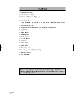
REAR PANEL
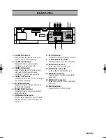
1. ALARM IN terminal
Input terminal to alarm recording. The
alarm sensor is connected here.
2. ALARM OUT terminal
Output terminal to indicate alarm
recording to an external alarm.
3. SERIES IN terminal
Input terminal to start/stop recording.
Also, use this terminal for series
recording or synchronous recording.
4. SERIES OUT terminal
Output terminal to use series recording or
synchronous recording.
5. TAPE END terminal
Output terminal to indicate when tape
has finished recording.
6. TRIGGER OUT terminal
Output terminal to control an external
camera switcher
7. GND(GROUND) terminal
When a lead connected other terminals
requires a ground, connect the ground
lead here.
8. KEY IN terminal
Wired remocon(option) jack in terminal.
9. 1- SHOT REC IN terminal
Input terminal to use 1-shot recording.
10. AUDIO IN connector
Audio input connector (RCA pin)
11. AUDIO OUT connector
Audio output connector(RCA pin)
12. VIDEO IN connector
Input connector for video signal (BNC
connector)
13. VIDEO OUT connector
Output connector for video signal (BNC
connector)
14. MIC IN terminal
Input connector for MIC (Mono)
Содержание HR24TLX
Страница 1: ...VIDEO CASSETTE RECORDER HR24TLX Installation Manual ...
Страница 33: ......


