Honeywell FF-SRM200P2 Скачать руководство пользователя страница 5

107111-11-EN FR26  GLO  503   Printed in Germany 

5


EXTENSION MODULES AND EXTERNAL
CONTACTORS


One or more FF-SRE Extension Modules or external safety
contactors with positive guided safety contacts can be used
to multiply the number of contacts of the FF-SRM200P2
module.


IMPROPER EXTERNAL SAFETY CONTACTOR
MONITORING


The proper operation of external safety contactors or
FF-SRE extension modules must be monitored using
the External Device Monitoring (EDM function of the
FF-SRM200P2 muting module). The correct operation of
the external contactors is then checked when pushing
the start push-button.


Refer to the application warnings and application
examples for details.

Failure to comply with this instruction could result in
death or serious injury.


LED INDICATORS


The FF-SRM200P2 module has 4 LED indicators: two
green LED relay status indicators (K1, K2) and two yellow
LED status indicator (Run 1, Run 2) on the front panel.


FIG 8.  LED INDICATORS


Relay outputs status (K1, K2)

Internal relays are energized
NO contacts are closed
NC contact is open

Internal relays are de-energized
NO contacts are open
NC contact is closed

light off

n-times flashing (error)

light on

flashing (0,66 Hz)

Diagnostic information (Run 1, Run 2)

Run 1

Run 2

or n

n

n

Normal operating

Waiting for restart

Application error

n

Fatal error


MODE SETTING

ELECTRICAL SHOCK
Remove power from the FF-SR safety control modules and
the machine during installation and before setup. Ensure
that installation is performed by qualified personnel.
Failure to comply with these instructions could result
in death or serious injury.


The operating modes of the FF-SRM200P2 module are set
using 4 selectors located behind the removable front panel.
60 different programs are available allowing to select the
muting modes, the mutual exclusion modes, the max.
muting time, the test mode (safety devices with or without
test input) and the External Device Monitoring (EDM)
modes.
The FF-SRM200P2 module has two redundant
microprocessor channels. The mode setting of each channel
is done by two selectors "A" and "B".
The position of the corresponding selector "A" or "B" for
channel 1 and channel 2 must be identical (see example).


Example: Selecting mode “31”


Selector

Channel 1

Channel 2

Description

"A"

3

3

Muting with 2 auxiliary sensors

"B"

1

1

Maximum muting time: 20 s


FIG 7. FRONT PANEL REMOVAL

Panel

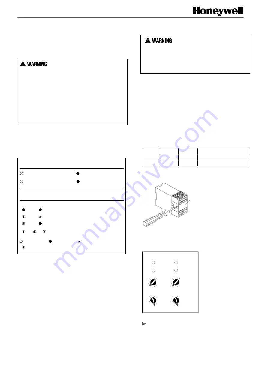
FIG 8. MODE SELECTOR “A” AND “B” FOR
CHANNEL 1 AND CHANNEL 2

Internal view

example "31"

channel 1

run1

K1

run2

K2

6

3

0

9

6

3

0

9

6

3

0

9

6

3

0

9

channel 2

Selector

"A"

Selector

"B"

F

S

RM

200_7

F

S

RM

200_8

F

S

RM

200_10

Содержание FF-SRM200P2

Страница 1: ...ut stopping the hazardous movement The FF SRM200P2 muting module has two internal safety relays with three normally open positive guided output contacts providing an emergency stop signal to the machine control circuitry The FF SRM200P2 helps to create a control reliable safety solution by providing redundancy and self checking circuitry Other features include a manual start mode an external devic...

Страница 2: ...e 2 0 45 0 70 0 85 1 Operating frequency 1200 switching cycles h max External fuse rating 6 A time delayed max Mechanical life Ten million switching operations Auxiliary outputs Relay status test output PNP static output 58 23 Vdc max 100 mA Test output Normally closed characteristics test active 0 Vdc test inactive 24 Vdc response of safety device on test signal 200 ms Muting lamp diagnostic outp...

Страница 3: ...TERMINAL BLOCKS run1 run2 K1 K2 CONTROL RELIABILITY Control Reliability essentially means that the device system or interface shall be designed constructed and interfaced such that any single component failure within the device interface or system shall not prevent normal stopping action from beeing applied but shall prevent the initiation of a successive operation until the failure is corrected O...

Страница 4: ...e The muting sensors must be installed so that only an object is able to validate a muting sequence but not a person When a valid muting sequence starts the output relay contacts of the FF SRM200P2 remain energised even if the protection field of the mutable safety devices is intruded by an object An external white muting lamp indicates that the safety device is actually muted Correct operation of...

Страница 5: ...hing 0 66 Hz Diagnostic information Run 1 Run 2 Run 1 Run 2 or n n n Normal operating Waiting for restart Application error n Fatal error MODE SETTING ELECTRICAL SHOCK Remove power from the FF SR safety control modules and the machine during installation and before setup Ensure that installation is performed by qualified personnel Failure to comply with these instructions could result in death or ...

Страница 6: ...1 SM2 1 mutable safety device No or 1 non mutable safety device 6 2 muting sensors SM1 SM2 1 or 2 mutable safety devices Selector A Muting modes Safety device with test input 7 2 start muting sensors SM1 SM2 2 end muting sensors EM1 EM2 1 mutable safety device 10 s 20 s 30 s 1 mn 5 mn 10 mn 30 mn 1 h 3 h 3 days Note 1 Activation of the mutable safety device s is are NOT necessary during muting seq...

Страница 7: ...ll safety devices are compatible with the FF SRM200P2 1 Without test input connection FF SYA type 4 safety light curtains FF SG type 4 safety light curtains FF SLG18147 and FF SLG30147 type 2 safety light curtain models FF SLG234 type 2 access detection light curtain FF SB type 4 safety light curtains FF LS type 4 safety light curtains FF SCAN type 4 modular light curtains FF SPS4 type 4 single sa...

Страница 8: ...nsor outputs with different potentials dc and dc When using sensors with static outputs connect one sensor with PNP output and one sensor with NPN output IMPROPER PUSH BUTTONS USE MANUAL START MODE To ensure proper use of an external start push button always design the circuitry for manual start mode compulsory in Europe only see application example page 7 Ensure the manual start push button and t...

Страница 9: ...wing conveyors C 2 x A B Lmax For safety related sensor positioning information refer to the Application Warnings Application description A conveyor is loading and unloading a hazardous zone guarded by two safety devices e g FF SB safety light curtain GK safety key interlock switch As the conveyor enters and exits the zone passing through the same opening the movement is bi directional The muting ...

Страница 10: ...ross fault detection between the input channels Note E External contactors when external contactors are used connect one normally closed contact of each contactor or the normally closed contact of the FF SRE extension module in series into the combined restart loop and External Device Monitoring EDM loop S43 S44 Install arc suppressors across the coils of external safety relays Functional descript...

Страница 11: ...nveyor e g palette Lmax maximum length of conveyor e g palette Distance A muting sensors SM1 SM2 A Vmin x 10 s Distance B muting sensors SM2 EM1 B Vmin x Tmaxmuting Lmax Distance C muting sensors EM1 EM2 No direct constraints but EM2 needs to be located so that all sensors SM and EM are free before the following conveyor starts a new valid muting sequence activating SM1 and SM2 Distance D between ...

Страница 12: ...evice Monitoring EDM loop S43 S44 Install arc suppressors across the coils of external safety relays Functional description Supply voltage A1 A2 Mutable Safety Device S11 S12 S13 S14 SM1 or SM2 SM2 or SM1 EM1 or EM2 EM2 or EM1 Relays K1 K2 Relay status output 58 Start P B Muting lamp 48 Restart Muting Muting Error 8 EM error Error 8 EM error 8 8 t 10 s t 3 s t t max Incorrect muting cyle Incorrect...

Страница 13: ... modes 30 to 39 example 3B 1 mutable e g FF SG safety light curtain and 1 non mutable safety device e g GK safety key interlock to monitor the safety door guard only select modes 20 to 29 2 auxiliary muting sensors SM1 and SM2 to start and end the muting sequence e g cam operated safety switches The use of the second mutable or non mutable safety device connectable to the same FF SRM200P2 module i...

Страница 14: ...t K4 4 4 Internal view channel 1 6 3 0 9 6 3 0 9 6 3 0 9 6 3 0 9 channel 2 Selector A Selector B Modes 30 to 39 muting with 2 muting sensors and 2 mutable safety devices Example mode 31 max muting time 20 s Note A Signals between redundant safety device inputs S11 to S14 or S21 to S24 must be applied within a max time of 2 5 s Modes 20 to 39 muting using safety devices without test input Unused sa...

Страница 15: ... used to evacuate the detection field see chapter Temporary Manual Muting Typical wiring diagram application example 3B Mode selector dc dc FF SRM200P2 A1 A2 M1 M2 48 Muting error restart S11 S12 S14 S13 A B C D D E E E B C S21 S22 S24 S23 13 23 K4 24 14 58 relay status S31 K1 K2 SM2 S32 machine control S34 S33 S41 S42 S44 S43 Fuses 6 A max Safety door K3 K3 Start K4 A B 1 A max 0 5 A max 2 7 1 6 ...

Страница 16: ...is activated by the translating cam at a position of minimum 6 mm above the BDC in Europe or inch above the BDC in North America Muting sensor SM1 must have been activated max 10 s before SM2 in order to have a valid muting sequence Install the second muting sensor EM2 in such way so that it gets de activated as soon as the press tool starts its closing stroke The first EM muting sensor getting de...

Страница 17: ...llowing the robot access to the hazardous area only when the operator is outside of it and has acknowledged exiting the area The mutual exclusion system is composed of the following elements the FF SRM200P2 muting module safety device 1 e g FF SYA safety light curtain 1 monitoring the access of the robot into the area safety device 2 e g FF SYA safety light curtain 2 monitoring the access of the o...

Страница 18: ... A Programmable Logic Controller PLC must NOT be able to override a manual start function Failure to comply with this instruction could result in death or serious injury Wiring diagram Mode selector dc dc FF SRM200P2 A1 A2 48 D D D error restart acknowledge S11 S12 S14 S13 A B A B S21 S22 S24 S23 13 23 K4 24 14 58 relay status B S31 K1 K2 S32 machine control S34 S33 S41 S42 S44 S43 1 A max Fuses 6...

Страница 19: ...fety output contacts when the push button is pushed longer than 3 s Pushing the start push button with one or both of the robot s safety devices activated leads to the energisation of the module output contacts 1 If safety device 2 operator is not activated OR 2 If safety device 2 has been activated but the operator has pushed the acknowledge push button to confirm that he has left the hazardous a...

Страница 20: ... SRE extension modules must be monitored using the External Device Monitoring EDM function of the FF SRM200P2 muting module The correct operation of the external contactors is so checked when pushing the start push button EDM muting modes connect one normally closed contact of each contactor or the normally closed contact of the extension module in series into the combined restart loop and Externa...

Страница 21: ...r and receiver needs to be powered AFTER the FF SRM200P2 muting module Otherwise the test sequence at power up may not work The connected safety devices must respond within max 200 ms after the generation of the test signal otherwise the module will display an error see Diagnostic Information Specifications of the test output Test output type terminal 58 PNP static output 24 Vdc max 100 mA Test ac...

Страница 22: ...odes 50 to 59 only 1 non mutable and 1 mutable safety device AND safety devices with test input the mutable safety device needs to be activated during the muting sequence Test input example 3 Muting using one FF SLG18 FF SLG30 type 2 safety light curtains with test input modes 50 to 69 dc dc FF SRM200P2 A1 A2 M1 M2 48 Muting error restart S21 S22 S24 S23 13 23 K4 24 14 58 S31 K1 K2 SM1 SM2 S32 mac...

Страница 23: ... 1 FF SLG emitter Test Fuse 1 A 6 1 Acknowledge P B auxiliary safety device for robot position B Note A Connect test output terminal 58 to the test input of each FF SGL18 FF SLG30 emitter as shown in the wiring diagram above while respecting the polarity of the test input terminals test input terminal 6 test input terminal 1 Note B Auxiliary safety device for robot position use is application depe...

Страница 24: ...e error is not resetable contact your nearest sales office for assistance 5 1 5 6 6 7 7 8 9 13 8 5 1 Mode selector error Different modes selected for channel 1 and channel 2 Not valid mode selection Select identical modes for channel 1 and channel 2 Select valid mode see mode selection table Under voltage error Supply voltage is too low 15 of nominal voltage 20 4 Vdc 6 Over voltage error Supply vo...

Страница 25: ...d or K4 Faulty push button Check EDM loop wiring Check and replace external contactor or push button power on of the module detection of a blocked start P B The start P B has been pushed for more than 3 s Check for short circuits in the start loop S43 S44 The start P B must be pushed and released within 3 s Max muting External device monitoring EDM error time error muting modes The selected max mu...

Страница 26: ...uting sequence All muting sensors SM EM and the safety devices must be de activated before a new muting sequence can be started 8 End muting sensor EM error 1 of the EM sensors was activated during module power up 1 of the EM sensors was activated during the start wait phase Muting modes with 4 muting sensors A new muting phase has been identified with 1 EM sensor not yet de activated Ensure EM se...

Страница 27: ...ustomer to determine the suitability of the product in the application Specifications may change at any time without notice The information we supply is believed to be accurate and reliable as of this printing However we assume no responsibility for its use SALES AND SERVICE For application assistance current specifications pricing or name of the nearest Authorized Distributor contact a nearby sal...

Отзывы: