


12
107111-11-EN FR26 GLO 503 Printed in Germany
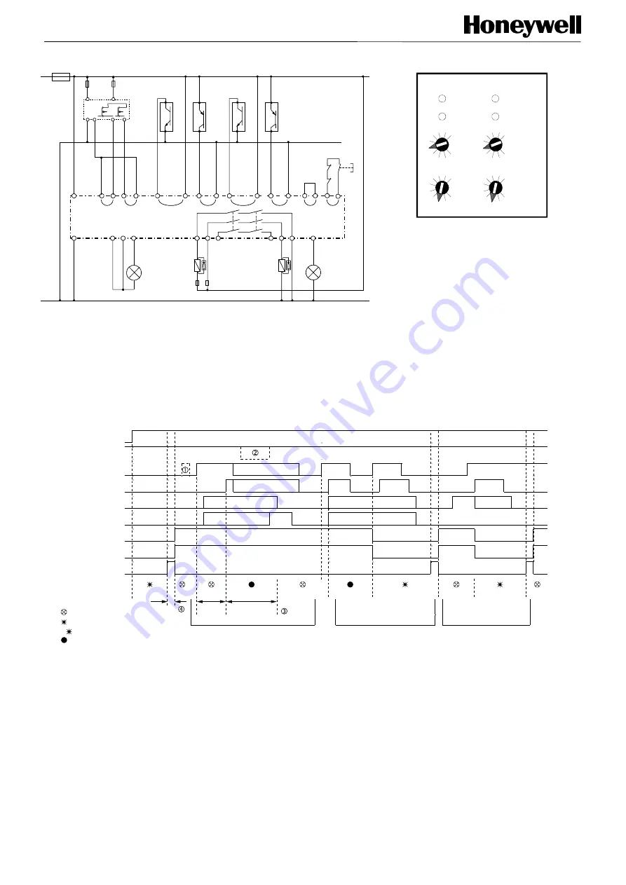
Wiring diagram
Mode selector
dc+
A1+
A2-
M1 M2 48
13
23 33
34
24
14
58
S11 S12 S14 S13
K1
K2
(A)
(B)
S41 S42 S44 S43
Start
dc-
muting /
error restart
K4
K3
machine
control
relay status
(B)
1 A
max.
0,5 A
max.
1
2 6
4
5
3
FF-SYA
Light
curtain
S31
S32
NPN
PNP
out
SM2
SM1
(C)
(C)
(D)
K3
K4
(D)
(D)
S34
S33
S21
S22
NPN
PNP
out
out
out
EM2
EM1
(C)
(C)
S24
S23
-
-
-
-
-
-
-
-
+ +
+
+
+
+
+ +
Internal view
channel 1
6
3
0
9
6
3
0
9
6
3
0
9
6
3
0
9
channel 2
Selector
"A"
Selector
"B"
Modes 40 to 49: muting with 2 start muting
sensors SM1, SM2, 2 end muting sensors
EM1, EM2 and 1 mutable safety device
without test input.
Example: mode 42: max. muting time 30 s.
Note (A):
Signals between redundant safety device inputs S11 to S14 must be applied within a max. time of 2.5 s.
Note (B):
Modes 70 to 79: muting using safety devices with test input: Terminal 58 is used as test output that must be connected to the
test input of the safety device (refer to chapter “Test input”).
Note (C):
Sensors contact type: this could be voltage free dry contacts or static contacts. When using sensors with static outputs, use 1
PNP and 1 NPN sensor to allow cross fault detection between the input channels. Use sensors with open outputs when no object is
detected.
Note (D):
External contactors: When external contactors are used, connect one normally closed contact of each contactor (or the normally
closed contact of the FF-SRE extension module) in series into the combined restart loop and External Device Monitoring (EDM)
loop S43/S44. Install arc suppressors across the coils of external safety relays.
Functional description
Supply voltage (A1/A2)
Mutable Safety Device
(S11/S12, S13/S14)
SM1 or SM2
SM2 or SM1
EM1 or EM2
EM2 or EM1
Relays K1, K2
Relay status output (58)
Start P/B
Muting lamp (48)
Restart
Muting
Muting
Error 8:
(EM error)
Error 8:
(EM error)
8
8
t<10 s
t<3 s
t < t
max
.
Incorrect muting cyle
Incorrect muting cyle
Correct muting cycle
: switched off
: flashing (0,66 Hz)
: switched on
: n-times flashing (error)
n
Notes:
•
Maximum coïncidence time between activation of muting sensors SM1 / SM2: 10 s (only the raising signal edge is taken into
account).
•
No timing constraints between EM1 / EM2.
•
Muting sensors can be activated in any order within the pair (SM1 then SM2 or vice-versa, EM1 then EM2 or vice-versa).
•
Once a valid muting sequence is started, both muting sensors SM1 and SM2 may be de-activated the muting sequence
without stopping the muting sequence in progress.
•
The de-activation of the first end muting sensor EM1 or EM2 will stop the muting sequence (only the falling signal edge is
taking into account).
•
tmax.: max. muting time programmable with the internal selector “B”.
•
The activation of only one sensor SM is ignored (see
Q
).
•
The activation of the mutable safety device is not necessary during a muting sequence (except modes 50 to 59) (see
R
).
•
All SM and EM sensors must be inactive before starting a new muting sequence (see
S
).
•
The restart push-button must be pushed AND released within 3 s to start the module (see
T
).
•
Activating the not mutable safety device leads to the de-energisation of the safety relay output of the module.
F
S
RM
200_18
F
S
RM
200_19
F
S
RM
200_20