


EP03-300-200
December,
2003
Release 200
Version 1.0
Experion PKS CEE-based Controller Specifications and Models
30
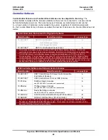
Table 15. CEE/CPM and CEE/ACE Processing Resources
Minimum Reserved overall CPU to be Maintained During
Runtime (CPUFREEAVG)
1
20% - CPM
40% - ACE
CEE type
PU Maximum
2
Maximum
Loading
Cycle
3
500 ms CEE - ACE
15000 PU/sec
60%
50 ms CEE – Non Redundant C200 Configuration
3600 PU/sec
60%
50 ms CEE – Redundant Configuration
1600 PU/sec
60%
5 ms CEE – Non Redundant Configuration
2400 PU/sec
40%
1
CPUFREEAVG is not supported on ACE; CPU Usage from Windows Task Manager provides the CPU Resources
used.
2
Available Processing Units at indicated maximum loading cycle percentage. For example, for a 50 ms non-
redundant CEE, users may configure it to use all of the 3600 PU. They must balance the CPU load across all
cycles. Once they have done so, no single cycle should exceed 60% in its CPUCYCLEAVG value.
3
Maximum Cycle Loading: Over cycles 0-39, the Average CPU Usage (CPUCYCLAVG) statistic is not to exceed
the stated maximums.
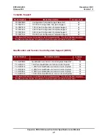
Table 16. CEE Memory Resources and Block Configuration
MU = Memory Unit = 1 Kbyte = 1024 bytes
C200/CPM
ACE
Maximum available memory resources
4000 MU
32000 MU
Maximum total number of CMs, SCMs and IOMs configurable per
CEE
1000 4000
(IOMs not
supported)
Maximum number of component blocks per CM
This maximum number is achievable under nominal operating and monitoring
conditions. The following items may lower the maximum number of FB's that
can be placed in or monitored from a single CM:
•
Monitoring frequently changing values
•
Operating in a redundant system
•
Operating with high quantities of configured peer-to-peer
40 40
Maximum number of Steps & Transitions (divided over all
handlers) per SCM
160
(80
Step/Transition
pairs)
160
(80
Step/Transition
pairs)


