Emergency Command Center Manual —
P/N LS10001-000FL-E:G 5/3/2016
51
Installation of Option Modules
Installation
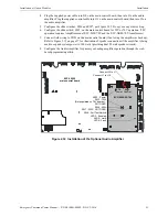
4. Plug the supplied power cable into J10 on the main control board, then into J1 on the audio
amplifier. Plug the supplied control cable into J11 on the main control board, then into J2 on
the audio amplifier.
5. Configure the slide switches, SW6 and SW7, per Figure 2.35. Do
not
use any other setting.
6. Configure the slide switch, SW5, on the main control board for 25V or 70V operation. (70V
operation requires Amplifier model ECC-50W-70V and the ECC-XRM-70V transformer.)
7. Connect field wiring to TB21 on the main control board (if not using the amplifier as backup).
Refer to Figure 2.15 on page 37 for illustration of speaker connections if the amplifier is being
used to expand system power to 100 watts (providing dual 50 watt speaker circuits).
8. Configure the Audio Amplifier for primary or backup amplifier operation through the web-
based programming utility.
J12
TB15
J9
+-
RTZM
Rev.
ECC-MCB-PCA
Figure 2.32 Installation of the Optional Audio Amplifier
ECC-50W-25/70V
ECC-50/100
main control board
b
d
a
m
n
t.
w
m
f
LED4 - Fault
LED2 - Limit
LED3 - Enabled
SW4 - Fail Test Switch
SW7 - 35W -
NOT USED
SW6 - 50W
SW5 - 75W
(Not populated on 70V boards) -
NOT USED
LED1 - Power
BDA
Power
BDA
Control
Connect J1 to J10
Connect J2 to J11
Содержание ECC-50/100
Страница 83: ...Emergency Command Center Manual P N LS10001 000FL E G 5 3 2016 83 Notes ...
Страница 95: ...Emergency Command Center Manual P N LS10001 000FL E G 5 3 2016 95 Notes ...
Страница 102: ...102 Emergency Command Center Manual P N LS10001 000FL E G 5 3 2016 Notes ...
Страница 106: ...106 Emergency Command Center Manual P N LS10001 000FL E G 5 3 2016 Slide in Labels ...
Страница 108: ...108 Emergency Command Center Manual P N LS10001 000FL E G 5 3 2016 Slide in Labels ...
Страница 114: ...Cut along dotted line ...
Страница 116: ...World Headquarters 1 Firelite Place Northford CT 06472 1653 USA 203 484 7161 fax 203 484 7118 www firelite com ...

