WEB-600E AND CP-600E NETWORK CONTROLLERS
13
62-0433—01
3.
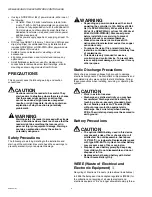
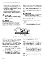
Replace the shield back onto the unit. To do this, care-
fully ease it over the port side first, then spring it down
over the other side. Make sure that its corner holes align
with the metal standoffs below.
4.
Refasten the four Phillips head screws that secure the
shield to the standoffs.
5.
Replace the plastic cover onto the unit.
POWER UP AND INITIAL
CHECKOUT
Ensure power wiring to the controller is ready—see the
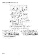
“Power Wiring” on page 8. See Fig. 3 for the location of status
LEDs and connectors. See Fig. 4 for the location of the NPB-
PWR-H module’s power connector.
After completing all mounting and wiring, do the following:
1.
2.
Also see the section “About Backup Configurations” on
Apply Power
To apply power, insert the power plug into either the NPB-
PWR-H module, or if using a NPB-WPM-US wall adapter, the
controller. If using the line-voltage input NPB-PWR-UN-H
power supply module, energize the 120–240Vac circuit wired
to the module.
CAUTION
Do not connect both the NPB-WPM-US and NPB-
PWR-H / NPB-PWR-UN-H supplies at the same
time, or equipment damage may result.
Check the Status LED
When power is applied, the green LED labeled “STATUS” will
light. This indicates that the system is OK and that power is
applied. Once the controller boots, the yellow “BEAT” LED
should start blinking, at a typical rate of 1Hz. Blinking should
begin about 30 seconds after power is applied.
If after applying power, the STATUS LED goes out, or if the
BEAT LED comes on (steady) and stays lit longer than 2
minutes, contact Systems Engineering for technical
assistance. See also “Status LEDs” on page 14.
ABOUT BACKUP
CONFIGURATIONS
A WEB-600E series controller allows two separate and
configurable methods to preserve unsaved station data when
"power quality events" occur, including loss of primary power
or low-voltage dips (brownout):
• Using the
integral
static RAM (SRAM) on the controller’s
NPM6E processor module. This default method can allow
the unit to operate “battery-less”, that is, without installing
the optional NiMH battery pack. Note in this configuration a
controller
reboot
is likely to occur whenever a power outage
or voltage dip is sustained for more than one AC line cycle
(1/50th or 1/60th of a second) or a number of line cycles,
depending on the load and power supply. Critical station
data will already be saved prior to any power quality event,
but the NiMH battery option is available to prevent
nuisance controller reboots/station restarts during
extended or frequent power outages.
• An
optional
on-board NiMH battery pack. Installing this
battery allows the controller to continue operation (without
rebooting) over short power outages or brownouts lasting
several seconds (or if also using SRAM, up to 10 minutes).
For longer duration outages, the battery allows the
controller to perform a “controlled shutdown”, safely
backing up the station before shutting down.
Starting in the AX-3.6.
nn
maintenance build, the controller can
use
both
the NiMH backup battery
and
available SRAM for
backup protection (prior to this, SRAM support required
removing
backup batteries). Configuring for
both
backup
battery and SRAM support provides the most comprehensive
backup protection. This allows the controller to “ride out” brief
power outages, while also protecting against a scenario of a
battery too weak (or aged) to perform a controlled shutdown.
SRAM
The WEB-600E controller’s NPM6E processor module
includes on-board SRAM and associated circuitry, allowing
“battery-less” operation. This is the same circuitry as provided
by the “SRAM option card” for earlier QNX-based Controllers,
available since the initial release of AX-3.6. Therefore, an
SRAM option card is
not needed
(or supported) in a WEB-
600E controller.
The default configuration is to use SRAM for station backup,
via the platform “DataRecoveryService” that is automatically
created in the controller’s running station. However, in some
cases, a station may be a poor candidate for SRAM support,
requiring too many resources by this associated platform
service. An example is a station with many rapidly changing
values all captured as histories, on COV. In this case, you may
wish to
disable
SRAM support, and install and use
only
the
optional NiMH battery pack.
For an overview, see “About Backup Configurations” on
page 13. Complete WEBs-AX details on the operation of the
WEB-600E’s integral SRAM are in the
WEB Data Recovery
Service (SRAM support)
- Engineering Notes
document.
NiMH battery pack
A custom 10-cell NiMH (nickel metal hydride) battery
assembly is available as a
separately orderable option
for the
WEB-600E controller. This battery assembly incudes a metal
bracket with the tie-wrapped NiMH battery pack. It is the same
battery assembly installed in the previous WEB-200/600, CP-
200/600 series controllers.
This battery allows the controller to continue station operation
through short power bumps, ranging from a few seconds to a
minute or more in duration (up to 10 minutes, if also using
SRAM). If a longer outage, the NiMH battery provides enough
run time for the unit to backup data and then shutdown.
Shutdown occurs automatically, after data is backed up to on-
board flash memory.
The controller charges the battery during normal operation,
until fully charged. Typically, the charge operation completes
within 18 hours. Following a power outage, the battery is
charged again, as necessary. The power and battery circuitry
is monitored by a station running on the controller (via its


