


WEB-300E, WEB-600E/U, CP-300E, CP-600E/U SERIES CONTROLLERS
5
31-00010—01
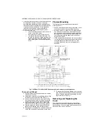
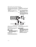
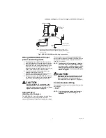
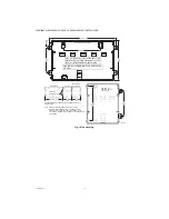
Fig. 2. Press in four tabs on ends of cover to remove.
NOTE: If accessory modules are plugged into the
controller, you may need to slide them away
from the unit to get to the end cover tabs.
• To remove the cover, press in the tabs on both ends of
the unit, and carefully lift it off.
• To replace the cover, orient it so the cutout area for
comm ports is correct, then push inwards to snap in
place.
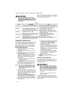
Board Layout
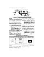
Fig. 3 shows the location of LEDs, option slots, and other
features of the 300E or 600E controller with cover
removed. For a side view of communications ports and
other features, see Fig. 6 on page 10.
Fig. 3. WEB and CP 300E or 600E Series controller main board layout details.
The controller ships with onboard static RAM (SRAM) that
can provide station backup during power loss, and also
has two (2) open option card slots for a variety of available
option cards. For details, see “About Expansion Options”
below, and also “About Backup Configurations” on
EXPANSION OPTIONS
The controller provides for field-installable expansion
using these types of options:
•
Option cards
— Install on connectors on the
controller’s base board. See “About Option Cards” on
•
Accessory modules
— To “chain” on the controller’s
20-pin connector. See “About Accessory Modules” on
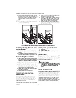
About Option Cards
The controller has two (2) available option slots for option
cards designed for use with controllers. Each slot has a
30-pin connector. Installing an option card is
recommended before mounting the unit. See “Installing
COVER
COVER TABS
(2 EACH END)
COVER
LIFTED
AWAY
M34985
PRESS IN TABS
PRESS
IN TABS
OPTION SLOT 2
COM 1
COM 2
SERIAL PORT LEDS ON BOTTOM
BOARD, REMOVE COVER TO SEE:
LAN2
(SEC)
LAN1
(PRI)
BEAT
STATUS
STATUS LEDS (VISIBLE WITH COVER ON):
BRACKET FOR
OPTIONAL
NIMH
BACKUP
BATTERY
OPTION SLOT
CONNECTORS
20-PIN
CONNECTOR
(I/O AND
POWER
MODULES)
MODE JUMPER
(FOR SERIAL
SHELL ACCESS)
SECONDARY
ETHERNET (RJ-45)
LAN2 (TOP BOARD)
RS-232 (DB-9)
COM1 (BOTTOM
BOARD)
PRIMARY
ETHERNET
(RJ-45) LAN1
(TOP BOARD)
RS-485
(3-POS.)
COM
(BOTTOM
BOARD)
NPM3E OR NPM6E
PROCESSOR MODULE
WITH INTEGRAL SRAM
BARREL POWER
CONNECTOR FOR
WALL MOUNTED
POWER MODULE
(WPM-XXX)
M34990
OPTION SLOT 1
EARTH GROUND
SPADE LUG
NORMAL
SERIAL SHELL