background image

LYNX BACNET PROGRAMMABLE, VAV/UNITARY CONTROLLERS – PRODUCT DATA 

EN0Z-0959GE51 R0615 

1.  Find an unused MAC address on the MS/TP network to 

which the LYNX controller connects. 

2.  Locate the DIP switch bank on the LYNX for addressing. 

This is labeled “MAC Address.” 

3.  With the LYNX Controller powered down, set the DIP 

switches for the MAC Address you want. Add the value of 
DIP switches set to ON to determine the MAC address. 
See Table 3. For example, if only DIP switches 1, 3, 5, 
and 7 are enabled, the MAC address would be 85 (1 + 4 + 
16 + 64 = 85). 

NOTE:


See Fig. 12 for DIP switch orientation and arrange-
ment. 

Table 3. DIP switch values for MS/TP MAC address 

DIP 

7 6 5 4 3 2 1 

VALUE 

64 32 16 8  4  2  1 


Setting the Device Instance Number 

The Device Instance Number must be unique across the 
entire BACnet system network because it is used to uniquely 
identify the BACnet devices. It may be used to conveniently 
identify the BACnet device from other devices during 
installation. The LYNX controller’s Device Instance Number is 
automatically set when it is added to a WEBStation-AX 
project. 
The Device Instance Number can be changed by the user, 
which may be necessary when integrating with a third party or 
when attempting to replace an existing controller and it is 
desired to maintain the existing Device Instance Number. 
To edit the Device Instance Number using WEBs AX: 
1.  Identify an unused Device Instance Number on the 

BACnet Network, in the range of 0 - 4194302. 

2.  Open the LYNX BACnet Device Mgr View 

a.  Double click on the BACnet Network located in the 

navigation tree. 

b.  Select the LYNX controller to be modified. 
c.  Click on the Edit button. 
d.  Enter an unused value in the Device ID field. 
e. Select OK 

3.  Right click on the LYNX Controller and select “Actions > 

Write Device Instance” to complete the update. 


Termination Resistors 

Matched terminating resistors are required at each end of a 
segment bus wired across (+) and (-). Use matched precision 
resistors rated ¼ W ±1% / 80…130 

. Ideally, the value of the 

terminating resistors should match the rated characteristic 
impedance of the installed cable. E.g., if the installed MS/TP 
cable has a listed characteristic impedance of 120 

, install 

120 

 matched precision resistors. 

NOTE:


LYNX controllers do not provide network biasing. 


Shield Terminating 

Following proper MS/TP cabling shield grounding procedures 
is important to minimize the risk of communication problems 
and equipment damage caused by capacitive coupling. 
Capacitive coupling is caused by placing MS/TP cabling close 
to lines carrying higher voltage. The shield should be 

grounded on only one end of the MS/TP segment (typically, 
on the router end). Tie the shield through using the SHLD 
(terminal 4) on the LYNX Controller. 
 

Sylk™ Bus 

Sylk is a two-wire, polarity-insensitive bus that provides both 
18 Vdc power and communications between a Sylk-enabled 
sensor and a Sylk-enabled controller. Using Sylk-enabled 
sensors saves I/O on the controller and is faster and cheaper 
to install since only two wires are needed and the bus is 
polarity-insensitive. Sylk sensors are configured using the 
latest release of the LYNX Tool for COACH

AX

1 2 3 4 5 6 7 8

1 2 3 4 5 6 7 8

1 2 3 4 5 6 7 8

9

9

9

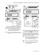
ADD APPROPRIATE TERMINATION RESISTOR

BETWEEN BAC+ BAC- TERMINALS.

SHI

E

L

D

SHI

E

L

D

SHI

E

L

D

B

AC +

B

AC +

B

AC +

BA

C -

BA

C -

BA

C -


Fig. 11. Termination modules (BACnet MS/TP daisy chain 

connections) 


Wiring Details 

Each controller is shipped with the digital outputs, which 
switch the 24 Vac to the load (high side). 
The three analog outputs (AO) are used to control modulating 
heating, cooling and economizer equipment. Any AO may be 
used as a digital output, as follows: 

  False (0%) produces 0 Vdc (0 mA) 

  True (100%) produces the max. 11 Vdc (22 mA) 

The wiring connection terminals described in Table 4 are 
shown in Fig. 12. 
 

IMPORTANT 

If the controller is not connected to a good earth 
ground, the controller's internal transient protection 
circuitry is compromised and the function of protecting 
the controller from noise and power line spikes cannot 
be fulfilled. This could result in a damaged circuit 
board and require replacement of the controller. See 
installation diagrams for specific wiring. 

 
All controllers have terminal arrangements similar to the 
example shown in Fig. 12 as described in Table 4. 
 

Содержание CentraLine LYNX BACnet CLLYUB1012S

Страница 1: ...nications Each controller has flexible universal inputs for wall modules digital inputs and a mix of analog and digital triac outputs see Table 1 The models CLLYVB6436AS CLLYVB0000AS and CLLYVB4022AS include an actuator Table 1 Controller configurations model type Universal Inputs UI Digital Inputs DI Analog Out puts AO Digital Out puts DO velocity pressure sensor Microbridge floating actuator CLL...

Страница 2: ... Analog voltage outputs Voltage output range 0 10 Vdc Max output current 10 0 mA UNIVERSAL INPUT UI CIRCUITS See Table 2 for UI circuit specifications Table 2 Universal input circuit specifications input type sensor type operating range Room Zone Discharge Air Outdoor Air Temp NTC 20kOhm 40 93 C Outdoor Air Temperature PT1000 IEC751 3850 40 93 C Resistive Input Generic 100 Ω 100 kΩ Voltage Input T...

Страница 3: ...ersal shaft adapter see Fig 1 UNIVERSAL SHAFT CLAMPING BOLTS 2 UNIVERSAL SHAFT ADAPTER MECHANICAL END LIMIT SET SCREWS 2 DECLUTCH BUTTON Fig 1 Floating actuator IMPORTANT Determine the damper rotation and opening angle prior to installation See Fig 2 and Fig 3 for examples DAMPER DAMPER SHAFT ROTATES CW TO OPEN Fig 2 Damper with 90 clockwise rotation to open IMPORTANT Mount actuator flush with dam...

Страница 4: ...gether to reduce the rotation travel c Tighten the two mechanical end limit screws Phillips 2 screwdriver 3 0 3 5 Nm torque d Using the DECLUTCH button rotate the universal shaft adapter fully CCW e Mount the actuator to the VAV damper box and shaft f Tighten the two bolts on the centering clamp 8 mm wrench 8 10 Nm torque g When the actuator closes the damper rotates CW either 45 or 60 to fully cl...

Страница 5: ...10 11 12 13 14 15 16 17 18 19 20 9 10 11 12 13 14 15 16 17 18 19 20 Fig 6 Panel mounting dimensions in mm S and NS models NOTE The controller is designed so that the cover does not need to be removed from the base plate for either mounting or wiring The controller mounts using four screws inserted through the corners of the base plate Fasten securely with four screws The controller can be mounted ...

Страница 6: ...ionships early in the job engineering process to ensure proper implementation when configuring the controllers See the controller Application Guides Power Budget A power budget must be calculated for each device to deter mine the required transformer size for proper operation A power budget is simply the sum of the max power draw ratings in VA of all the devices to be controlled This includes the ...

Страница 7: ...wiring recommendations see section Power on page 6 1 2 3 4 5 6 7 8 1 2 3 4 5 6 7 8 1 2 3 4 5 6 7 8 9 9 9 OUTPUT DEVICE POWER TRANSFORMER 120 240 VAC COM 24 VAC EARTH GROUND TERMINAL 3 EARTH GROUND TERMINAL 3 EARTH GROUND TERMINAL 3 EARTH GROUND WHEN CONNECTING POWER TO THE LYNX BACnet CONTROLLER CONNECT THE COM LEG OF THE VAC SECONDARY CIRCUIT TO A KNOWN EARTH GROUND CONNECT POWER TO TERMINALS 1 A...

Страница 8: ...e rated characteristic impedance of the installed cable E g if the installed MS TP cable has a listed characteristic impedance of 120 Ω install 120 Ω matched precision resistors NOTE LYNX controllers do not provide network biasing Shield Terminating Following proper MS TP cabling shield grounding procedures is important to minimize the risk of communication problems and equipment damage caused by ...

Страница 9: ...t present The actuator is internally hardwired to these terminals C Analog outputs may be configured as digital outputs and operate as follows FALSE 0 0 Vdc 0 mA TRUE 100 the max 11 Vdc 22 mA D Digital inputs open circuit FALSE closed circuit TRUE UI 1 is selectable as a fast digital pulse meter Table 5 Description of wiring terminals CLLYVB0000AS CLLYVB4022AS and CLLYVB6436AS TERMINAL LABEL CONNE...

Страница 10: ...gital inputs see Fig 17 Typical controller wiring for 4 20 mA heating cooling and model ML6161 floating motor control see Fig 18 Typical controller wiring for a pneumatic transducer model RP7517B see Fig 19 24VAC BACnet MS TP BACnet MS TP SHIELD 24VAC COM REHEAT STAGE 3 REHEAT STAGE 2 OR CLOSE REHEAT STAGE 1 OR OPEN DAMPER CLOSE DAMPER OPEN C770A AIR TEMP SENSOR AIR FLOW PICK UP WINDOW CONTACTS CO...

Страница 11: ...LVE ACTUATOR PWM VALVE ACTUATOR PWM OUTPUT FROM CONTROLLER PWM H 24 VAC T5 T6 C B W R 24 N 24 H 2 3 3 3 2 1 3 4 ON OFF ML7984B CONFIGURATION DIP SWITCHES LOCATED ADJACENT TO THE INPUT TERMINAL BLOCK PERIPHERAL HEAT VALVE ACTUATOR ML7984B REHEAT VALVE ACTUATOR CLLYUB6438S DO 1 DO 2 DO 4 DO 6 DO 8 COM COM COM COM DO 3 DO 5 DO 7 BAC BAC 24VAC 20VDC EGND S BUS S BUS 24VAC COM AO 1 DI 1 DI 2 AO 2 AO 3 ...

Страница 12: ...her 4 20 mA signal devices Place this resistor as close as possible to the driven device CLCM4T111 WALL MODULE GND SENSOR SET POINT BYPASS LED 5 6 7 4 3 2 1 1 2 3 4 5 6 7 8 9 0 1 2 3 4 5 6 7 8 9 0 2 2 2 2 2 2 2 2 2 2 3 3 3 3 3 3 3 3 3 4 1 2 3 4 5 6 7 8 1 1 1 1 1 1 1 1 1 1 2 1 2 3 4 5 6 7 8 9 0 0 9 CLLYUB6438S 24 VAC 24 VAC COM E GND SHLD SBUS1 SBUS2 NET 1 NET 2 DO 1 DO 2 COM COM COM COM DO 3 DO 4 ...

Страница 13: ...g diagram CLLYUB6438S shown with 4 20 mA heating cooling and ML6161 damper actuator NOTE 1 Earth ground wire length should be held to a minimum Use the heaviest gauge wire available up to 14 AWG 2 0 mm 2 with a minimum of 18 AWG 1 0 mm 2 for earth ground wire NOTE 2 Ensure that all transformer power wiring is as shown Reversing terminations will result in equipment malfunction 1 2 3 4 5 6 7 8 9 0 ...

Страница 14: ...ee Fig 11 Correct placement of the end of line termination resistors is required for proper BACnet MS TP Bus communications Step 2 Startup See Fig 20 and the following text for startup information CLLYVB6438NS DO 1 DO 2 DO 4 DO 6 DO 8 COM COM COM COM DO 3 DO 5 DO 7 BAC BAC 24VAC 20VDC EGND S BUS S BUS 24VAC COM AO 1 DI 1 DI 2 AO 2 AO 3 COM COM COM DI 3 DI 4 20VDC UI 1 COM UI 2 UI 3 COM UI 4 UI 5 C...

Страница 15: ...vere injury death or property damage Do not attempt to modify the physical or electrical characteristics of this device in any way If trouble shooting indicates a malfunction replace the controller WARNING Electrical Shock Hazard Can cause severe injury death or property damage To prevent electrical shock or equipment damage disconnect power supply before beginning controller replacement Terminal ...

Страница 16: ... proceed as follows 1 Remove all power from the controller 2 Remove the two air flow pickup connections from the pressure sensor 3 Remove the terminal blocks see section Terminal Block Removal 4 Remove the old controller from its mounting IMPORTANT IN THE CASE OF CONTROLLERS MOUNTED TO A DIN RAIL 1 Push straight up from the bottom to release the top pins 2 Rotate the top of the controller outwards...

Отзывы: