


EAGLEHAWK NX CONTROLLER – INSTALLATION & COMMISSIONING INSTRUCTIONS
EN1Z-1039GE51 R1218
8
LEFT (GREEN) LED
LIT CONTINUOUSLY = LINK ACTIVE
LINK INACTIVE
"
"
DARK = "
"
RIGHT (YELLOW) LED
LIT CONTINUOUSLY = "100 Mbaud"
DARK = "10 Mbaud"
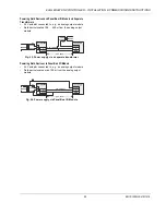
INTER-
FACE 2
INTER-
FACE 1
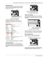
Fig. 9. Ethernet / RJ45 sockets
NOTE:
The Ethernet / RJ45 sockets are usually earth-
grounded. For additional information, see also
"Appendix 1: Earth Grounding" on pg. 51.
The two Ethernet interfaces can be used in either of two
different ways (the corresponding configuration is done in
COACH NX):
• "Separated networks" (factory default). In this scenario,
each of the two Ethernet interfaces must be activated and
located in a different subnet.
• "Switch functionality." In this scenario, one of the two
Ethernet interfaces is deactivated. The deactivated Ether-
net interface now functions in the loop-through (daisy-
chain) mode and can therefore be used to continue the
data line.
NOTE:
During any power failure of the EAGLEHAWK NX,
the switching functionality is inoperative.
DNSv4 Servers
DNS Domain
Host Name
Host File
IPv4 Gateway
192.168.1.1
Physical Address
Description
ID
Interfaces
Ipv4 Settings
DHCPv4
IPv4 Address
IPv4 Subnet Mask
DHCPv4 Server
Ipv6 Settings
TCP/IP Configuration
TCP/IP Configuration
fec1
Local Ethernet Adapter 2
00:30:AF:FF:04:61
Enabled
Interface 1
Interface 2
Adapter Enabled
Enabled
Remote File System
Application Director
Certificate Management
Distribution File Installer
File Transfer Client
Lexicon Installer
License Manager
Platform Administration
Software Manager
Station Copier
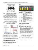
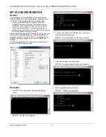
Fig. 10. Entering gateway address, disabling one of the
two Ethernet interfaces in COACH NX
To ensure that the discovery of devices, datapoints,
schedules, and histories does not fail, you should enter a
gateway address. If there is no gateway address physically
given by the Network Setting, then enter a gateway address
that relates to the IP address of the enabled Ethernet Inter-
face. In Fig. 10, the gateway address is 192.168.1.1, hence
the IP address of Ethernet adapter 1 must be in the range of
192.168.1.2 to 192.168.1.255.
Default IP Addresses of Ethernet Interfaces 1 and 2
In any case, the default IP address of Ethernet interface 1 is:
192.168.200.20, mask 255.255.255.0
and the default IP address of Ethernet interface 2 is:
192.168.201.20, mask 255.255.255.0
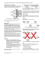
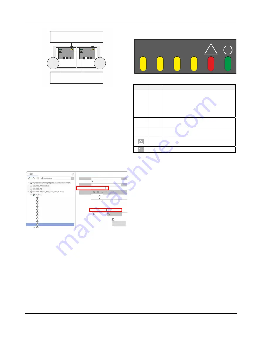
LEDs
The EAGLEHAWK NX controller features the following LEDs:
L1 L2 Tx Rx
!
Fig. 11. EAGLEHAWK NX controller LEDs
Table 4. EAGLEHAWK NX controller LEDs
symbol
color
function, description
L1
yellow
Lit = Daemon starting; flashing = station
starting; if L2 is also flashing, then the
station has started.
L2
yellow
Lit = platform has started / is reachable;
flashing = station has started / is
reachable.
Tx
yellow
RS485-1 status LED indicating trans-
mission of communication signals.
Rx
yellow
RS485-1 status LED indicating reception
of communication signals.
!
red
Indicates an active alarm; is controlled by
Niagara Alarm System; is configurable.
green
Power LED.
See also section "EAGLEHAWK NX Controller Trouble-
shooting" on page 49 for a detailed description of the
behaviors of the LEDs and their meanings.
RS485 Interfaces
General
The EAGLEHAWK NX controller features two RS485
interfaces:
• RS485-1 (consisting of push-in terminals 24 [GND-1], 25,
and 26) is isolated and can be used for any RS485-based
communication protocol available within Niagara
Ecosystems, e.g.: Panel Bus, BACnet MS/TP, etc.
• RS485-2 (consisting of push-in terminals 29, 30, and 31
[GND-2]) is non-isolated (i.e. GND-2 is internally con-
nected with terminal 1 [24V~0]) and can be used for any
RS485-based communication protocol available within
Niagara Ecosystems, e.g.: Panel Bus, BACnet MS/TP,
etc.
NOTE:
It is imperative that the RS485-2 be powered by a
power supply having the proper polarity. Failure to do
so will make data transmission impossible.
Configuring the RS485 Interfaces in COACH NX
When you configure the two RS485 interfaces (for Modbus,
BACnet MS/TP, or Panel Bus) in COACH NX, the cor-
responding Port Names will appear as shown in Fig. 12.