


EAGLEHAWK NX CONTROLLER – INSTALLATION & COMMISSIONING INSTRUCTIONS
EN1Z-1039GE51 R1218
28
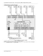
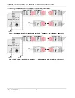
Binary Outputs
The EAGLEHAWK NX features eight (CLNXxxx26xxx) or four
(CLNXxxx14xxx) binary outputs arranged in two blocks
(BO1…4 and BO5…8, respectively).
WARNING
Risk of electric shock or equipment damage!
Low voltage and line voltage must not be wired within
the same block.
In the event of an application stop (e.g., during application
download), the binary outputs assume the safety positions
configured in COACH NX.
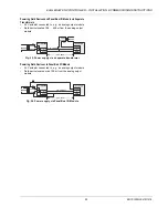
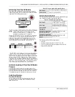
The polarity (normal = N.O. contact or reverse = N.C. contact)
configuration defines if a relay is open or closed, depending
upon whether there is a logical 1 or a logical 0. This is done
by selecting (in COACH NX) one of the following options:
normal (default)
state=1 → relay contact is closed
state=0 → relay contact is opened
reverse
state=0 → relay contact is closed
state=1 → relay contact is opened
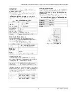
Table 16. Relay specifications of the EAGLEHAWK NX
block 1
block 2
BO1…3
BO4
BO5…8
contact volt. AC
5…253 V
5…253 V
5…253 V
contact volt. DC
5…30 V
20…30 V
5…30 V
max. contact cur-
rent AC (resistive)
3 A
10 A
3 A
max. contact cur-
rent AC (induct.)
0.3 A*
10 A
0.3 A*
max. contact cur-
rent AC (induct.)
2 A**
10 A
2 A**
max. contact cur-
rent DC
3 A
7 A
3 A
min. load
100 mA /
5 VDC
40 mA /
24 VDC
100 mA /
5 VDC
* typically 250,000 cycles; ** typically 50,000 cycles
NOTE:
The total max. sum load for all binary outputs
(BO1…8) equals 14 A.
NOTE:
Binary output 4 supports the switching of high in-rush
currents (e.g., motors, incandescent lights, etc.). The
max. allowed switch current is 80 A for a duration of
max. 20 ms.