


EAGLEHAWK NX CONTROLLER – INSTALLATION & COMMISSIONING INSTRUCTIONS
EN1Z-1039GE51 R1218
6
Bus and Port Connections
Overview
WARNING
Risk of electric shock or equipment damage!
►
Do not touch any live parts in the cabinet!
►
Disconnect the power supply before making connections
to or removing connections from terminals of the
EAGLEHAWK NX controller or Panel Bus I/O modules.
►
Do not reconnect the power supply until you have
completed installation.
►
Due to the risk of short-circuiting (see Fig. 23), it is
strongly recommended that the EAGLEHAWK NX con-
troller be supplied with power from a dedicated trans-
former. However, if the EAGLEHAWK NX controller is to
be supplied by the same transformer powering other con-
trollers or devices (e.g., the PW M-Bus Adapter), care
must be taken to ensure that correct polarity is observed.
►
Observe the rules regarding electrostatic discharge.
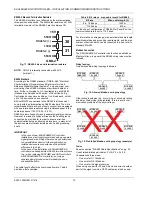
24V
-0
24V~
1
7
8
2
9
DO1
DO
2
DO3
IN
IN
4
DO
4
DO5
IN
5
IN
6
DO6
DO7
IN
7
IN
8
DO8
GND
AO1
AO
2
AO3
5
6
7
8
9 10
11 12 13 14 15 16 17 18
19 20 21 22
AO
4
23
24 25 26
27 28 29 30 31 32
5
6
GN
D1
485-
1+
48
5-
1-
n.a.
n.a.
GN
D2
485-
2+
48
5-
2-
n.a.
1
2
3
4
R
S
232
RS485-1
EN
D
BI
AS
MI
D
BI
1
BI
2
BI
3
BI
4
GN
D
UI
1
UI
2
UI
3
UI
4
UI
5
UI
6
UI
7
33 34 35 36 37
38 39
40 41 42 43 44 45 46
UI
8
47
UI
9
UI
10
2
1
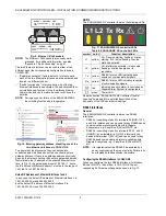
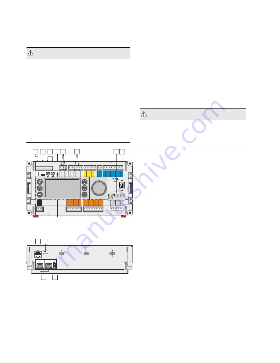
Fig. 2. Top view (with HMI and full complement of
onboard I/Os)
1
2
EN
D
BI
AS
MI
D
4
3
Fig. 3. Side view
Legend
1 RS232 / RJ45 socket (for connection of M-Bus and
other RS232-based protocols; factory debugging)
2 Three-position slide switch (for setting bias and
termination resistance of RS485-1)
3 Two Ethernet / RJ45 sockets (for BACnet IP com-
munication); 10/100 Mbit/s; 1 "link" LED + 1 "activity"
LED
4 USB 2.0 Host Interface (for connection of IF-LON2);
max. 200 mA, high speed
5 RS485-1* (isolated; for BACnet MS/TP, Panel Bus,
Modbus RTU communication, etc.)
6 RS485-2* (non-isolated; for BACnet MS/TP, Panel
Bus, Modbus RTU communication, etc.)
7 LEDs
8 USB 2.0 Device Interface (for connection to COACH
NX web browsers, and 3
rd
-party touch panels)
9 HMI (or RJ45 socket for connection of portable HMI)
*Modbus RTU Master/Slave communication is possible on the
two RS485 interfaces.
WARNING
Risk of electric shock or equipment damage!
►
It is prohibited to connect any of the RJ45 sockets of the
EAGLEHAWK NX controller to a so-called PoE-enabled
device ("
P
ower
o
ver
E
thernet").