Honeywell BCU 460 Скачать руководство пользователя страница 80

BCU 460, BCU 465 · Edition 11.19

80

Parameters

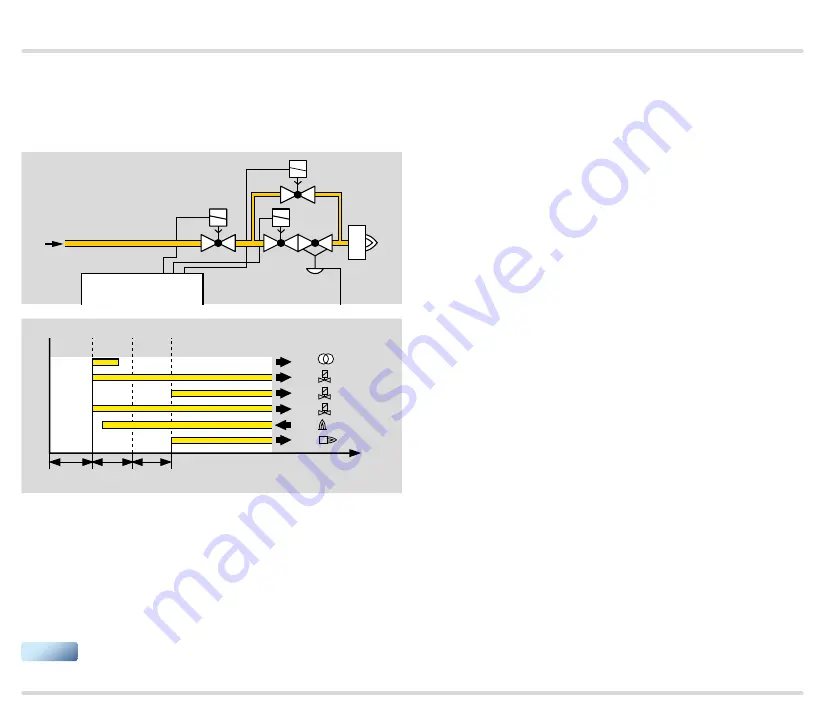
Parameter A078 = 4: two-stage burner 1. Three valves 
(V1, V2 and V3) are included for a two-stage burner. 

These are connected to the valve outputs (terminals 60, 

61 and 62).

BCU 46x

µC

V1

V2

V3

61 62

60

52

55

54

53
56

47 48

58

03

02

01

04

2

1

3

t

t

FS1

t

SA1

t

BP

1

51

61
62

60

22

96

Valves V1 and V3 open to start the burner. The burner 

is started with a limited ignition capacity using gas 
valve V3. After the flame proving period t

FS1

 has 

elapsed, valve V2 opens to enable the 2

nd

 gas stage.

If a previous version is replaced by the BCU 4, param-
eter A078 = 4 must be selected in any event.

Содержание BCU 460

Страница 1: ... a further option of using the furnace chamber temperature Simple system integration using the PC programming and diagnostic software BCSoft With optional valve proving system With optional operating modes to reduce thermal NOx Fieldbus connection PROFIBUS PROFINET EtherNet IP using optional bus module Burner control units BCU 460 BCU 465 ...

Страница 2: ...onization control in double electrode operation 24 3 2 5 BCU 460 P3 E1 LM 400 F3 E1 with industrial plug for ionization control in double electrode operation 25 3 2 6 BCU 465 P3 E1 LM 400 F3 E1 with industrial plug for ionization control in double electrode operation 26 3 2 7 Flame control 27 3 2 8 Assignment of connection terminals 28 3 3 BCU 460 program sequence 30 3 4 BCU 465 program sequence 3...

Страница 3: ... 100 11 9 2 Relief valve VPS 100 11 9 3 Measurement time for Vp1 101 11 9 4 Valve opening time tL1 101 11 10 Behaviour during start up 102 11 10 1 Minimum pause time tMP 102 11 11 Manual mode 102 11 11 1 Operating time in Manual mode 102 11 12 Sensors 103 11 12 1 Function of sensor 1 103 11 12 2 Function of sensor 2 104 11 12 3 Function of sensor 3 105 11 12 4 Proof of closure function test period...

Страница 4: ...set 127 15 7 External securing bars 127 15 8 Bus module BCM 400 127 15 9 Flange plates 128 16 BCM 400 129 16 1 Application 129 16 2 Function 129 16 3 Electrical connection 129 16 4 Commissioning 131 16 5 Selection 132 16 6 Technical data 132 17 Technical data 133 17 1 Electrical data 133 17 2 Mechanical data 134 17 3 Ambient conditions 135 17 4 Dimensions 135 18 Converting units 136 19 Safety spec...

Страница 5: ... To be continued 23 12 Safe failure fraction SFF 143 23 13 Diagnostic coverage DC 143 23 14 Mode of operation 143 23 15 Probability of dangerous failure PFHD 144 23 16 Mean time to dangerous failure MTTFd 144 Feedback 145 Contact 145 ...

Страница 6: ...ce control by taking over tasks that relate to the burner for example it ensures that the burner ig nites in a safe condition when it is restarted The air control on the BCU F1 or F3 assists the furnace control for cooling purging and capacity control tasks The burner control unit has an interface via which an air valve or actuator can be controlled for staged or modu lating burner capacity contro...

Страница 7: ...operation Using the BCSoft program the parameters analysis and diagnostic information can be read from a BCU via the optionally available opto adapter If necessary the device parameters can be adjusted easily using BCSoft All valid parameters are saved on an integrated param eter chip card The parameter chip card can be removed from the old unit and inserted into a new BCU to trans fer the paramet...

Страница 8: ...The gas air mixture is adjusted to the requirements of the applications using the parameters of pre ventila tion and post ventilation The pressure switch moni tors the air flow in the air supply line or in the flue gas exhaust BICR VG L VR R BCU 465 F3 60 61 3 DI L1 N PE µC P 4 1 81 82 95 96 A P 35 2 6 65 36 HT Start1 PLC ...

Страница 9: ...tion system PLC to the BCU BCM for starting resetting controlling the air valve purging the furnace or for cooling and heating during operation In the op posite direction it sends operating status the level of the flame signal and the current program status Control signals that are relevant for safety such as the safety interlocks purge and HT input are wired inde pendently of the bus communicatio...

Страница 10: ...tput at ter minal 65 and moves the butterfly valve to the ignition position condition the IC 40 must have reached the ignition position on the instant of ignition The burner starts The burner application Burner 1 with pilot gas pa rameter A078 1 is selected so that the burner can be started with a limited start fuel flow rate To activate the high fire rate DI 2 is actuated via the air valve output...

Страница 11: ...ition condition the IC 40 must have reached the ignition position on the instant of ignition The burner starts The burner application Burner 1 with pilot gas pa rameter A078 1 is selected so that the burner can be started with a limited start fuel flow rate During operation the BCU activates DI 1 and DI 2 using outputs 65 and 66 This enables the analogue input IN on the actuator IC 40 Depending on...

Страница 12: ...1 3 P 35 6 HT PLC Control ON OFF or High Low The BCU provides the cooling and purging processes Parameter A078 4 is selected so that the two stage burner starts at low fire rate When the operating state is reached the BCU advises the control unit Depend ing on the parameter setting the air valve on terminal 65 is actuated to open and close by the program or ex ternally via the input at terminal 4 ...

Страница 13: ... 35 2 6 65 36 HT Start1 PLC Control ON OFF The BCU provides the cooling and purging processes The variable air gas ratio control compensates for gas air pressure fluctuations Optional the pressure switch monitors the air flow during pre purge and operation The gas air mixture is adjusted to the requirements of the application using the parameters of pre ventilation and post ventilation ...

Страница 14: ... HT output that the furnace system is in High temperature mode HT When the HT input is activated the burner control units switch to High temperature mode They operate without evaluat ing the flame signal and their internal flame control is non functional If the furnace temperature falls below the spontaneous ignition temperature 750 C the FCU disconnects the HT output from the electrical power sup...

Страница 15: ...d by actuator IC 40 and butterfly valve BVH An air pressure switch upstream of the burner monitors the functioning of the butterfly valve In addition air gas ratio monitor ing for the zone or the furnace is required As soon as the safety temperature monitor STM signals a furnace temperature of 850 C 1562 F the burner can be switched to flameless combustion Low NOx mode to significantly reduce NOx ...

Страница 16: ...rgical industry With ON OFF cyclic control the capacity supplied to the process is controlled by means of a variable ratio of the operating time to the pause time In this type of control the burner output pulse frequency always maintains full momentum and results in maximum convection in the furnace chamber even with regulated heating M PZL PZH PZ PZL PDZ TE M BCU 460 LM F3 BCU 460 LM F3 FCU 500 F...

Страница 17: ...e ignition and monitoring of the individual burners is ensured by burner control unit BCU 460 with power module LM F3 The centrally checked safety func tions such as pre purge tightness test flow detector and pressure switch check gasmin gasmax airmin are provided by the FCU 500 M PZL PZH PZ PZL PDZ TE M BCU 460 LM F3 BCU 460 LM F3 FCU 500 F0 µC P DG DG DG VAS VAS VAS VCG VCG VR L VR L DG DG DGmin...

Страница 18: ...re that the correct air vol ume is available for ignition start fuel flow rate when starting the burners the FCU sends the burner start enable signal to the BCUs via the LDS limits during start up output The circuit design of the safety interlock and LDS outputs on the FCU and the corresponding in puts on the BCUs ensures that the burners can only start if the safety interlocks and the LDS output ...

Страница 19: ...ective 2014 30 EU EMC Electromagnetic Compatibility Directive EU 2016 426 GAR Gas Appliances Regulation EN 13611 2015 AC 2016 EN 1854 2010 class S FM approved Factory Mutual FM Research Class 7610 Combus tion Safeguards and Flame Sensing Systems Suitable for applications pursuant to NFPA 86 www approvalguide com Eurasian Customs Union The products BCU 460 and BCU 465 meet the techni cal specificat...

Страница 20: ...eplaceable 10 M5 screw terminal for burner ground There are two control keys for the control unit OK ON OFF Use the ON OFF key to switch the control unit on or off Reset Information The control unit is reset to its starting position in the event of a fault using the Reset Information button During operation the LED display 1 shows the program status The flame signal intensity the fault history and...

Страница 21: ...2 53 BM 55 25 N1 56 26 N1 F1 BCU E1 1 N1 N1 N1 N1 N1 N1 N1 N1 pU 2 230 V UVS I Z 3 1 2 4 6 5 7 40 41 35 39 LDS Start 1 F2 BCU E0 HT PE PE PE PE BCU 460 Function 3 2 Connection diagram 3 2 1 BCU 460 E1 LM 400 F0 E1 with ionization control in double electrode operation Alternative flame control see page 27 Flame con trol Electrical connection see page 121 Project planning information Explanation of ...

Страница 22: ...25 N1 56 26 N1 1 N1 N1 N1 N1 N1 N1 N1 N1 pU 2 230 V UVS I Z 3 1 2 4 6 5 7 40 41 35 39 P LDS Start 1 A HT PE PE PE PE PE 65 34 66 vLuft N1 67 BCU 460 F 3 15 A F1 BCU E1 F2 BCU E0 Function 3 2 2 BCU 460 E1 LM 400 F3 E1 with ionization control in double electrode operation Alternative flame control see page 27 Flame con trol Electrical connection see page 121 Project planning information Explanation ...

Страница 23: ...6 N1 1 N1 N1 N1 N1 N1 N1 N1 N1 pU 2 230 V UVS I Z 3 1 2 4 6 5 7 40 41 35 39 P LDS Start 1 A HT PE PE PE PE PE 65 34 66 vLuft N1 67 DW 2 DW 1 PE PE BCU 465 F 3 15 A F1 BCU E1 F2 BCU E0 FLO Function 3 2 3 BCU 465 E1 LM 400 F3 E1 with ionization control in double electrode operation Alternative flame control see page 27 Flame con trol Electrical connection see page 121 Project planning information Ex...

Страница 24: ...E1 1 N1 N1 N1 N1 N1 N1 N1 N1 pU 2 230 V UVS I Z 3 1 2 4 6 5 7 40 41 35 39 F2 BCU E0 PE PE PE PE BCU 460 15 6 7 9 10 14 16 11 12 8 L1 N PE HT 16 15 14 12 11 10 9 8 7 6 4 2 1 1 1 Function 3 2 4 BCU 460 P3 E1 LM 400 F0 E1 with industrial plug for ionization control in double electrode operation Alternative flame control see page 27 Flame con trol Electrical connection see page 121 Project planning in...

Страница 25: ...S I Z 3 1 2 4 6 5 7 40 41 35 39 PE PE PE PE PE 65 34 66 vLuft N1 67 BCU 460 F 3 15 A F1 BCU E1 F2 BCU E0 L1 N PE HT 16 15 14 12 11 10 9 8 7 6 4 3 P A 2 2 1 1 15 6 6 6 3 6 4 7 9 10 14 16 11 12 2 8 LDS Function 3 2 5 BCU 460 P3 E1 LM 400 F3 E1 with industrial plug for ionization control in double electrode operation Alternative flame control see page 27 Flame con trol Electrical connection see page ...

Страница 26: ...2 4 6 5 7 40 41 35 39 PE PE PE PE PE 65 34 66 vLuft N1 67 DW 2 DW 1 PE PE BCU 465 F 3 15 A F1 BCU E1 F2 BCU E0 6 6 6 3 6 4 7 9 10 14 16 11 12 2 8 LDS FLO 15 L1 N PE HT 16 15 14 12 11 10 9 8 7 6 4 3 P A 2 2 1 1 Function 3 2 6 BCU 465 P3 E1 LM 400 F3 E1 with industrial plug for ionization control in double electrode operation Alternative flame control see page 27 Flame con trol Electrical connection...

Страница 27: ...S 5 10 or flame detectors for continuous operation UVC 1 Ionization control in single electrode operation Parameter I004 0 52 22 PE BM Z 51 21 BM PE N1 230 V UVS 1 UVS control Parameter A001 5 A Parameter I004 1 UVS 1 2 3 52 22 PE BM Z 51 21 BM PE N1 230 V UVS 1 UVC control Parameter I004 2 UVC 1 4 3 2 1 54 24 PE BM 22 Z 51 21 BM PE N1 1 N1 ...

Страница 28: ...ates without evaluating the flame signal The safety function of the device s internal flame control system is deactivated The furnace chamber temperature is monitored by a safety temperature monitor STM 35 Controller enable Emergency stop Connection for higher level safety devices and interlocks e g emergency stop 39 LDS query Feedback signal of the control element position for ignition capacity A...

Страница 29: ... an actuator LM F3 65 66 67 Air valve control Connections for air valves 80 81 Floating contact Fault signal Contact between terminals 80 81 and 82 closes in the event of a BCU fault lock out 82 95 Operation Contact between terminals 95 and 96 closes once the operating signal has been received from burner 1 Contact between terminals 95 and 97 closes once the operating signal has been received from...

Страница 30: ...94 running ignition in process valves for 1st gas stage open and min operating time starts to elapse A061 If no flame detected max 3 start up attempts A007 or fault lock out 03 Flame proving period 1 tFS1 running A095 In the event of flame failure fault lock out 04 Operation signalling contact closes valve for 2nd gas stage opens and min operating time tB starts to elapse A061 In the event of flam...

Страница 31: ...ng A036 or pre purge running 01 Min pause time running again parameterA062 Flame simulation check if parameter A003 1 A1 Pre ventilation time tVL running A036 A2 Safety time 1 tSA1 running A094 ignition in process valves for 1st gas stage open and min operating time starts to elapse A061 If parameter A048 1 air valve opens with 1st gas stage If no flame detected max 3 start up attempts A007 or fau...

Страница 32: ...ut down via ϑ signal A0 If min operating time tB has elapsed operation signalling contact opens gas valves close and running time A042 starts to elapse Over run time post ventilation tNL running A039 00 Air actuator is closed running time starts to elapse A042 ...

Страница 33: ...th LM F3 valve are actuated for this purpose by the capacity control system of the BCU After being enabled by the protective system the BCU can start the burners The capacity is controlled during operation by an external temperature control system VAS M PZL PZH PZ PZL PDZ TE M FCU 500 F0 µC P DG DG DG VAS VAS VCG VCG VR L VR L DG DG DGmin DGmax 49 15 13 14 50 45 47 48 58 750 pu 2 DLmin DLPurge BCU...

Страница 34: ...rge time the control element moves to the ignition position Once the protective system terminal 35 safety interlocks has issued the enable signal the burner can be started by the start up signal at termi nal 1 The control element can be activated to control the burner s capacity dependent on parameters A048 and A049 Modulating control Parameter I020 2 A048 2 After the operating signal has been rec...

Страница 35: ...rge time if there is adequate air flow After the elapse of the pre purge time the air valve closes for ignition Once the protective system terminal 35 safety inter locks has issued the enable signal the burner can be started by the start up signal at terminal 1 The gas valves for the 1st stage are opened and the burner is ignited on the BCU C1 after a successful valve check After the operating sig...

Страница 36: ...ted using a pressure regulator e g VAD The gas volume is set using a fine adjusting valve e g VMV The air volume for the operating modes is set by adjusting the butterfly valve e g BVH The air pressure is monitored on each burner by a pressure switch to check the functioning of the butterfly valve In addition air gas ratio monitoring for the zone or the furnace is required since the air pressure s...

Страница 37: ...ion chamber The oxidation reactions take place without a vis ible flame Compared to traditional Flame mode the reac tion zone is considerably larger and the reaction density considerably lower This prevents the occurrence of peak temperatures which are responsible for high NOx values Emissions of NOx are drastically reduced 850 1050 1250 1200 1150 1100 900 1000 950 0 100 200 300 400 Furnace temper...

Страница 38: ...7 FLO PLC Parameters A006 3 A074 1 and A078 0 must be set to switch to Low NOx mode The BCU D2 must signal via terminal 6 that the required temperature for high temperature operation has been reached A higher switching point of 850 C is required for flameless operation Flameless mode is enabled via the input at terminal 7 depending on parameter A064 the system is either switched over immediately o...

Страница 39: ...out as the furnace temperature falls the BCU automatically switches from Flameless mode to Flame mode To avoid a pressure surge in the gas supply due to several burners being switched off at the same time it is recommended that the furnace control unit switches the burners to Flame mode again zone by zone for example Hot air compensation and ratio control are not the re sponsibility of the BCU The...

Страница 40: ...able signal is issued For details see page 40 Tightness control 6 1Tightness control The aim of the tightness control is to identify an inad missible leak on one of the gas solenoid valves and to prevent burner start Gas solenoid valves V1 and V2 are tested as is the pipework between the valves V2 pu Vp1 V1 PZ pu 2 European standards EN 746 2 and EN 676 stipulate tightness controls for capacities ...

Страница 41: ...s solenoid valve during this check The burner is ignited when pre purge is ended and the tightness has been checked successfully After burner shut down After the burner has been shut down the BCU checks the tightness of the gas solenoid valves and the pipe work between them Once the test has been carried out successfully the next burner start is enabled The BCU immediately conducts a tightness tes...

Страница 42: ...measurement time tM the tightness control checks the pressure pZ between the valves If pressure pZ is less than half the inlet pressure pu 2 valve V2 is leaking If pressure pZ is greater than half the inlet pressure pu 2 valve V2 is tight Valve V2 is opened for the set opening time tL V2 closes again During the measurement time tM the tightness control checks the pressure pZ between the valves If ...

Страница 43: ... tightness control checks the pressure pZ between the valves If pressure pZ pu 2 valve V1 is leaking If pressure pZ pu 2 valve V1 is tight Valve V1 is opened for the set opening time tL V1 closes again During the measurement time tM the tightness control checks the pressure pZ between the valves If pressure pZ pu 2 valve V2 is leaking If pressure pZ pu 2 valve V2 is tight The tightness test can on...

Страница 44: ...60 61 38 36 37 pu 2 TC PZ PZL PDZ 750 ϑ 1 3 2 pu 2 PZ Vp1 V1 V2 pu pz pd The test period tP is calculated from Opening times tL for V1 and V2 Measurement times tM for V1 and V2 tP s 2x tL 2x tM 6 1 4 Opening time tL Standard EN 1643 2000 allows a maximum opening time of 3 s for the tightness test if the main gas valves are actuated directly If gas can flow into the combus tion chamber when a valve...

Страница 45: ... calculated from Inlet pressure pu mbar Leakage rate QL l h Test volume Vp1 l Calculation of the test volume see page46 Test volume Vp1 For one test volume Vp1 between 2 gas solenoid valves Adjustable using parameterA056 tM s 2 x pu x Vp1 QL For a large test volume Vp1 with reduced testing time Adjustable using parameterA056 tM s 0 9 x pu x Vp1 QL Conversion into US units see page 136 Converting u...

Страница 46: ...0 3 VAS 6 1 37 25 0 5 VAS 7 2 04 40 1 3 VAS 8 3 34 50 2 VAS 9 5 41 65 3 3 VG 10 0 01 80 5 VG 15 0 07 100 7 9 VG 20 0 12 125 12 3 VG 25 0 2 150 17 7 VG 40 VK 40 0 7 200 31 4 VG 50 VK 50 1 2 250 49 VG 65 VK 65 2 VG 80 VK 80 4 VK 100 8 3 VK 125 13 6 VK 150 20 L Vp1 VV L x VR Valves Pipe Type Volume VV l DN Volume per metre VR l m VK 200 42 VK 250 66 The measurement time required for the test volume V...

Страница 47: ...2 47 48 TC PZL PDZ 750 1 3 2 Vp1 VAS 665 VAS 665 pu 50 mbar Q N max 200 m3 h DN65 9 5 m Leakage rate QL 200 m3 h x 1000 l h 200 l h 1000 x 1 m3 h Test volume Vp1 1 1 l 9 5 m x 3 3 l m 32 45 l see page46 Test volume Vp1 Measurement time for one test volume Vp1 tM s 2 x 50 mbar x 32 45 l 16 23 s 200 l h Set the next highest value 20s using parameter56 see page101 Measurement time for Vp1 ...

Страница 48: ... PDZ M 750 ϑ 1 2 V1 V2 38 GZL By checking the closed position using the proof of clo sure function the BCU complies with the requirements of NFPA 85 Boiler and Combustion Systems Hazards Code and NFPA 86 Standard for Ovens and Furnaces 6 2 1 Program sequence When the start up signal is received at terminal 1 the BCU checks that the valve is in its closed position using the POC switch If a signal i...

Страница 49: ...sioning support in order to fa cilitate the commissioning process In the event of faults or service interventions details on troubleshooting can be derived from the device statistics and the fault history The current version of the engineering tool BCSoft is available at www docuthek com In addition to the engineering tool BCSoft an opto adapter with USB connection or a Bluetooth adapter is requir...

Страница 50: ...plications without functional safety They are bus variants for fieldbus communication optimized for speed and low connec tion costs 1 2 3 L1 BUS FCU P HT PROFINET BCM BCU 4xx BCM BCM BCU 4xx BCU 4xx PLC The basic function of fieldbus communication is the exchange of process and required data between a con troller e g a PLC and several distributed devices e g BCM with BCU The signals from the devic...

Страница 51: ...s on the front for connection to the fieldbus The RJ45 connection sockets are combined with an internal 2 port switch This allows the BCM 400 together with the BCU to be integrated in various network topologies star tree or line topology Requirements such as Auto Negotiation and Auto Crossover are satisfied Safety related signals and interlocks e g safety inter lock must be wired independently of ...

Страница 52: ...nufacturer for PROFIBUS and PROFINET in a device master data file GSD file or for EtherNet IP in an electronic data sheet EDS The GSD EDS file is required to integrate the device BCU in the con figuration of the PLC The GSD EDS file contains the device image the communications properties and all fault messages from the device in text form which are important for configuring the PROFINET network an...

Страница 53: ...terrupted and during initialization of the bus communication after switching on the digital signals are interpreted as 0 8 3 1 Modules for process data All modules required for data exchange between the PLC and the burner control unit BCU are shown in the following table Module PROFINET Slot Inputs BCU PLC 1 Outputs PLC BCU Burner 1 flame signal 2 Burner 2 flame signal 3 Status signal 4 Fault and ...

Страница 54: ...L 7 Manual mode Burner 2 flame signal Free BOOL Output bytes PLC BCU The output bytes describe the digital signals which are output by the PLC to the BCU The digital signals to control the burner control unit BCU occupy 2 bytes 16 bits Terminals 1 to 41 dependent on parameters I061 to I074 can be wired parallel to the bus communication This allows the BCU to be controlled using the digital signals...

Страница 55: ...rred from the BCU to the PLC as an analogue value using this module The flame signal occupies one byte with values from 0 to 255 flame signal from 0 to 25 5 µA Bit Byte n Data type Format Value 0 1 2 3 4 5 6 7 Burner 2 flame signal Byte DEC 0 2551 0 25 5 μA 1 See code tables BusCommunication_BCU4_R2 xlsx at www docuthek com Status signal BCU PLC This module transfers the status signals from the BC...

Страница 56: ...te n 2 Byte n 3 Data type Format Value 0 1 2 3 4 5 6 7 Warning signals Word DEC 0 6555351 1 See code tables BusCommunication_BCU4_R2 xlsx at www docuthek com Remaining times BCU PLC This module transfers the remaining times of various processes from the BCU to the PLC The remaining time occupies one word Bit Byte n Byte n 1 Data type Format Value 0 1 2 3 4 5 6 7 Remaining times Word DEC 0 6554 0 6...

Страница 57: ... Close control element Free BOOL BCU output information BCU PLC This module transfers the signal states of the digital outputs on the BCU via output terminals and bus to the PLC Bit Byte n Byte n 1 Byte n 2 Byte n 3 Byte n 4 Byte n 5 Format 0 Terminal 60 Terminals 80 81 82 Ready Burner 1 operating signal Control element to max position Flameless mode ON1 BOOL 1 Terminal 61 Terminals 85 86 87 Purge...

Страница 58: ...1001 Parameter 1002 Counter statistics 1003 Fault warning statistics 1004 Operator statistics counters 1005 Operator statistics faults warnings 1006 Event history 1007 Power module statistics 1008 Extreme values statistics 1009 Time counter statistics 1010 Operator statistics extreme values 1011 Operator statistics time counters The available data records differ in terms of their indexes The conte...

Страница 59: ... Free 6 Free 7 Free I O bytes the programmer can choose the data to be transferred Inputs Outputs 460 465 basic I O 1 byte 1 byte 460 465 standard I O 4 bytes 1 byte 480 basic I O 1 byte 1 byte 480 standard I O 5 bytes 1 byte Baud rate up to 1500 kbit s The max range per segment depends on the baud rate Baud rate kbit s Range m 93 75 1200 187 5 1000 500 400 1500 200 The specified ranges can be inc...

Страница 60: ... capacity closed position2 A Approaching maximum capacity2 P1 Pre purge internal A Approaching ignition capacity2 HX Delay in program step X Valve check 02 Safety time 1 A2 Safety time 1 with air 03 Flame proving period 1 tFS1 A3 Flame proving period 1 tFS1 with air 04 Burner 1 operation controller enable A4 Burner 1 operation controller enable with air 09 Over run up to minimum capacity P9 Post p...

Страница 61: ...alled back to terminal40 or41 Simultaneous Min Max bus command E 24 Open actuator and Close actuator bus signals set simultaneously Non fail safe parameters NFS inconsistent E 30 NFS parameter range is inconsistent Fail safe parameters FS inconsistent E 31 FS parameter range is inconsistent Mains voltage E 32 Operating voltage too high low Faulty parameterization E 33 Parameter set contains illega...

Страница 62: ...l error E 95 Error at digital outputs Internal error E 96 Error when checking the SFR No PCC power module error E 97 Insert compatible PCC rectify power module contact error Internal error E 98 Error when writing to the EEProm emBoss E 99 Shut down without application error Minimum capacity not reached E A Position for minimum capacity has not been reached after 255s Maximum capacity not reached E...

Страница 63: ...odule Invalid configuration 2 The bus module has received an incorrect configuration from the controller Invalid network name 3 Invalid network name or no address allocated in the network name Controller in STOP position 4 Controller in STOP position Burner 1 flame simulation E A1 Burner 1 flame simulation while air actuator is open No flame after safety time 1 E A2 No flame during safety time 1 w...

Страница 64: ...4 2 20µA where I004 0 5 or 7 5 20µA where I004 1 3 or 8 5µA where I004 2 4 or 6 Flame simulation check in standby position A003 0 1 Off On 0 High temperature operation A006 0 3 6 Off Continuous operation Burner 1 UVS Burner 2 ionization 0 Burner 1 start up attempts A007 1 2 3 1 start up attempt 2 start up attempts 3 start up attempts 1 Restart A009 0 1 4 Off Burner 1 Burner 1 max 5 x in 15 min 0 D...

Страница 65: ...ion Opens with gas stage 1 Opens with gas stage 2 Opens with V4 burner 1 0 Air actuator can be activated externally on start up A049 0 1 Cannot be activated Can be activated externally 0 Air actuator in the event of fault A050 0 1 Cannot be activated Can be activated externally 1 Valve proving system A051 0 1 2 3 Off Tightness test before start up Tightness test after shut down Tightness test befo...

Страница 66: ...dby in CLOSED position MIN to MAX capacity standby in position for MIN capacity burner quick start IGNITION to MAX capacity standby in CLOSED position burner quick start 0 Auxiliary gas function A077 0 1 2 3 Off Flame mode Flameless operation Operation 0 Burner application A078 0 1 4 13 Burner 1 Burner 1 with pilot gas Two stage burner 1 Flameless 1 0 with 2 gas paths 0 Fieldbus communication A080...

Страница 67: ... 5 6 7 8 9 10 11 12 13 14 15 32 33 34 35 48 49 50 51 52 53 54 55 56 No function APS Purge APS Stage 1 APS Purge Stage 1 APS Stage 2 APS Purge Stage 2 APS Stage 1 Stage 2 APS Purge Stage1 Stage2 APS Flameless APS Purge Flameless APS Stage 1 Flameless APS Purge Stage1 Flameless APS Stage 2 Flameless APS Purge Stage2 Flameless APS Stage 1 2 Flameless APS Purge Stage1 2 Flameless APS External Low APS ...

Страница 68: ...ription Factory default settings Active cooling outputs A129 0 1 2 3 4 5 6 7 Off Air actuator Cooling air Air actuator cooling air Flue gas Air actuator flue gas Cooling air flue gas Air actuator cooling air flue gas 1 Over run time flameless tNL A139 0 60 s Time in seconds 0 ...

Страница 69: ... for burner 1 and UVC control for burner 2 UVC control for burner 1 and ionization control for burner 2 UVC control for burner 1 and UVS control for burner 2 0 Air actuator I020 0 2 5 Off IC 40 Air valve 0 Function of terminal 64 I040 0 2 3 Off V5 Bus output 1 0 Contact 80 81 82 function I050 0 1 2 3 4 5 6 7 Off Ready signal Air signal Purge signal Cooling air valve Flue gas valve Fault signal Bur...

Страница 70: ...r signal Purge signal Cooling air valve Flue gas valve Fault signal Burner 1 operating signal 7 Contact 85 86 87 function I054 0 1 2 3 4 5 6 7 Off Ready signal Air signal Purge signal Cooling air valve Flue gas valve Fault signal Burner 1 operating signal 2 Function of input 1 I061 0 4 5 6 7 8 9 11 12 13 14 17 19 Off Safety interlocks Air Cooling air Air actuator R1 Air actuator R2 Start 1 Reset P...

Страница 71: ...8 9 11 12 13 14 17 19 Off Sensor 1 Sensor 2 Sensor 3 Safety interlocks Air Cooling air Air actuator R1 Air actuator R2 Start 1 Reset Purge LDS start up conditions High temperature operation Flameless operation Auxiliary gas 0 on BCU 460 1 on BCU 465 Function of input 37 I070 See I069 See I069 0 on BCU 460 2 on BCU 465 Function of input 38 I071 See I069 See I069 0 on BCU 460 3 on BCU 465 Function o...

Страница 72: ...ory all the parameters of the BCU can be scanned in numeri cal order by repeatedly pressing the Reset Information button for 1 s The parameter display is ended 60 seconds after the last time the button is pressed or by switching off the BCU The BCU indicates when the mains switch has been switched off The parameters cannot be scanned when the BCU is switched off or when a fault or warning is displ...

Страница 73: ...burner 1 is dependent on the setting of interface parameter I004 Flame control I004 0 ionization control 2 20 µA I004 1 control using UVS sensor 5 20 µA I004 2 control using UVC sensor 5 µA 11 4 2 Burner 2 flame signal FS2 switch off threshold Parameter A002 The sensitivity at which the burner control unit still detects a flame at burner 2 can be set using param eter A002 As soon as the measured f...

Страница 74: ...rt 1 Start 1 Parameter A003 1 flame simulation check on start up The flame simulation check is conducted after ap plying the start up signal start 1 during the waiting time tW What is flame simulation Flame simulation means that an extraneous signal is detected as a flame signal out of sequence If the BCU detects such an extraneous signal during the flame simulation check it starts the flame simul...

Страница 75: ...e mode 750 C the flame may be controlled via the temperature using a safety temperature monitor STM in order to increase the system s availability This means that no incorrect flame signals e g signals from a UV sensor which interprets reflected UV radiation as extra neous signals may lead to faults FCU 500 H1 M HT 18 HT HT BCU 46x D1 6 22 µC BCU 46x D1 6 22 µC 5 8 STM When the HT input is activat...

Страница 76: ... the HT input terminal 6 so as to activate High temperature mode tSA1 tZ 8888 04 02 03 00 ϑ t tFS1 V1 V2 V3 HT L1 1 35 L 51 22 60 61 62 6 96 82 If the temperature in the furnace chamber drops below 750 C the HT input must be disconnected from the electrical power supply and the furnace must then be operated with flame control The BCU then responds depending on setting Parameter A006 0 Off The High...

Страница 77: ... L1 1 35 L 51 22 60 61 62 6 96 82 The BCU switches off the burner and restarts with flame simulation check recommended in the case of UV control with UVS If no flame signal is present when High temperature mode is deactivated the burner control unit performs a fault lock out regardless of parameter A006 04 t E 04 88 ϑ L1 V1 V2 V3 HT 1 35 L 51 22 60 61 62 6 96 82 ...

Страница 78: ...00 t E 04 8888 ϑ L1 V1 V2 V3 1 35 L 51 22 60 61 62 96 82 If no flame is formed during the start up so that at the end of the safety time tSA1 no flame signal is detected this will result in a BCU safety shut down with subse quent fault lock out The fault message E 04 will flash in the BCU display depending on the burner operating mode Parameter A007 2 3 2 or 3 start up attempts tSA1 tZ 02 00 t 01 ...

Страница 79: ... 56 47 48 58 03 02 01 04 2 1 3 51 61 62 60 22 96 t tFS1 tSA1 tBP 1 Parameter A078 1 burner 1 with pilot gas Three valves V1 V2 and V3 are included for a burner with a pilot gas valve These are connected to the valve out puts terminals 60 61 and 62 Valves V1 and V3 open to start the burner The burner is started with a limited ignition capacity using gas valve V3 After the elapse of the safety time ...

Страница 80: ...BCU 46x µC V1 V2 V3 61 62 60 52 55 54 53 56 47 48 58 03 02 01 04 2 1 3 t tFS1 tSA1 tBP 1 51 61 62 60 22 96 Valves V1 and V3 open to start the burner The burner is started with a limited ignition capacity using gas valve V3 After the flame proving period tFS1 has elapsed valve V2 opens to enable the 2nd gas stage If a previous version is replaced by the BCU 4 param eter A078 4 must be selected in a...

Страница 81: ...erent gas paths in Flame mode and Flameless mode FCU Process Control PCC PZL BCU 465 F3 µC 36 V2 61 62 60 6 7 HT V3 V1 FLO 65 VR N PLC STM In Flame mode 850 C the burner is started con ventionally with the pre ventilation time tVL defined in parameter A036 03 02 04 2 1 3 t tFS1 tSA1 tVL PZL 51 61 62 60 6 1 7 36 42 65 HT ϑ FLO ...

Страница 82: ...r Flameless mode must be supplied to the BCU from a separate control unit terminal 7 In Flameless mode 850 C the burner is started with the pre ventilation time tVLM defined in parameter A028 No ignition using the transformer takes place during safety time tSA1 The gas valves V1 and V3 are opened at the start of the safety time tSA1 03 02 04 t tFS1 tSA1 tVLM 65 2 1 3 PZL 51 61 62 60 6 1 7 36 42 HT...

Страница 83: ...ock out A007 1 or with one or two ad ditional start up attempts A007 2 or 3 The BCU will complete a maximum of three start up attempts Safety time 1 must be determined on the basis of cur rent national standards and regulations The burner application and the burner capacity are the main cri teria for this If the ϑ signal terminal 1 drops out during safety time 1 the valves will not be switched off...

Страница 84: ...unt national standards and require ments it must be clarified whether the restart func tion may be used In accordance with EN 746 2 a restart may be con ducted only if the safety of the installation is not im paired The precondition for an automatic restart is that the burner can restart as intended in all operating phases In this case it must be ensured that the program se quence started by the B...

Страница 85: ...ubsequent fault lock out being performed The BCU has a safety shut down with subsequent fault lock out option if more than 5 restarts are performed within a period of 15 minutes Taking into account national standards and require ments it must be clarified whether the option may be used 11 6 2 Minimum operating time tB Parameter A061 A minimum operating time 0 to 250 s may be defined to ensure that...

Страница 86: ...ding on param eter A077 Parameter A077 0 Off The valve is not opened Parameter A077 1 Flame mode In Flame mode valve V4 is opened as long as the auxiliary gas signal is re ceived at one of the terminals and the BCU is operating Parameter A077 2 flameless operation In Flameless mode valve V4 is opened as long as the auxiliary gas signal is received at one of the terminals and the BCU is operating P...

Страница 87: ...t down properties can be set using param eter A016 If the air pressure falls below the value set on the airmin air pressure switch the signal to terminal 36 is interrupted and the BCU initiates a reaction depend ing on the parameter setting When the air actuator is switched off the no flow state default position of the air pressure switch PDZ is checked BCU µC P 38 pe 2 TC 36 PDZ If air flow monit...

Страница 88: ...s of 1 s Prolonging the safety time during operation increases the instal lation availability in the case of brief duration signal fades e g fades of the flame signal The requirements of national standards and regula tions must be satisfied In accordance with EN 298 the maximum reaction time to a flame failure must not exceed 1 s Specific ap plication standards may permit other values In accordanc...

Страница 89: ...switch e g function of sensor 1 parameter A101 1 3 5 7 9 11 13 and 15 the pre purge time is counted as soon as all the pres sure switches in use have switched Without a pressure switch the pre purge time starts as soon as the air ac tuator has reached the purge position 11 8 2 Pre ventilation time tVL Parameter A036 This parameter is used to define the length of time dur ing which the air valve is...

Страница 90: ... for minimum maximum capacity The running time set using parameter A042 is activated for approaching these positions see page 91 Running time After this time has elapsed the BCU will initiate the next pro gram step Parameter A041 2 On for approaching the position for maximum capacity The running time set using pa rameter A042 is activated for approaching the position for maximum capacity see page ...

Страница 91: ... closed before a start up is initiated 11 8 6 Over run Parameter A043 The over run tKN supports applications with a pneu matic air gas ratio control system and On Off control Using the over run function reduces the O2 content in the furnace atmosphere 00 A4 t tKN A 88 ϑ V1 V2 L1 1 35 L 51 22 60 61 96 82 65 4 Parameter A043 0 Off No over run is performed The gas circuit is closed immediately owing ...

Страница 92: ...or until the air actuator is closed The gas valves are closed immediately in the event of a flame failure A flame failure during the over run does not result in a fault lock out Parameter A043 3 low fire over run time bound BCU 460 F3 µC VAS VAG VR L V1 V2 61 60 22 66 U V S The burners are initially powered down to low fire rate and remain in operation for the programmed duration depending on para...

Страница 93: ...048 0 opens on external activation tSA tZ A042 A4 02 03 00 A0 t tFS H1 88 A ϑ V1 V2 1 1 35 L 51 22 60 61 96 82 65 4 66 M This setting together with parameter A049 0 see page 95 Air actuator can be activated externally on start up is required for burners on which the air gas ratio is controlled by a pneumatic air gas ratio control system and which need to be started at low fire rate e g on two stag...

Страница 94: ...82 65 4 66 M tSA tZ A4 A2 A3 00 A000 t tFS A0 The air actuator opens at the same time as the first gas stage with V1 Parameter A048 2 opens with gas stage 2 operating fuel flow rate tSA tZ A4 02 03 00 t tFS 00 A0 88 A ϑ V1 V2 1 1 35 L 51 22 60 61 V3 62 96 82 65 4 66 M The air actuator opens simultaneously with the second gas stage operating signal ...

Страница 95: ...r actuator can be activated externally via the input at terminal 4 during start up Parameter A048 must be set to 0 for this purpose see also page 93 Air actua tor control 11 8 9 Air actuator in the event of fault Parameter A050 This parameter decides whether the air actuator can be activated externally via the input at terminal 4 in the event of a fault lock out Parameter A050 0 cannot be activate...

Страница 96: ...nal ϑ has been applied and the no flow state check has been conducted successfully the air valve is opened Start up of the burner com mences with no interruption of the air supply after ex piry of the programmable pre ventilation time tVLM Parameter setting for this example sequence A074 1 A016 0 see also page 87 Delayed low air pressure protection The gas valve does not open until the pressure sw...

Страница 97: ...rt up will be continued until the end of the minimum operat ing time If the signal at terminal 7 drops out during the flame less start up or operation the burner will be switched off immediately If the start up signal continues to be applied a burner start may be performed in Flame mode depending on the other parameters Parameter A064 2 immediate switchover As soon as there is a signal at the Flam...

Страница 98: ...inputs terminals 6 and 7 must receive a signal to switch to Flameless mode The timing of the switchover is con trolled by the parameter Flameless operation A064 In Flame mode 850 C the burner is started con ventionally as with A078 0 with the pre ventilation time tVL defined in parameter A036 The air control valve is in the high position for Flame mode 03 02 04 2 1 51 61 60 6 1 7 36 t tFS1 tSA1 tV...

Страница 99: ...eried via terminal 36 Parameter A074 2 High temperature operation with out ignition If the BCU is in High temperature mode the ignition ignition transformer will not be activated for the start up 11 8 13 Over run time flameless tNL Parameter A139 00 A0 A4 t tNL A 88 ϑ V1 V2 V3 PZL 1 1 35 L 51 22 60 61 62 96 82 36 65 4 In Flameless mode the actuator air valve actuator will remain open for the progr...

Страница 100: ... 1 tightness test before start up Parameter A051 2 tightness test after shut down With this setting a tightness test is also performed af ter a fault is reset and after mains on Parameter A051 3 tightness test before start up and after shut down An additional bypass valve must be installed in gas sec tions with an air gas ratio control This valve allows the closed air gas ratio control to be bypas...

Страница 101: ...s See also page 45 Measurement time tM 11 9 4 Valve opening time tL1 Parameter A059 This parameter is used to define the opening time for the valves 2 to 25 s which are opened to fill or dis charge the test volume between the gas valves If the preset opening time tL 3 s is inadequate e g if slow opening valves are used to fill the test volume or re duce the pressure between the valves bypass valve...

Страница 102: ...r flow terminal 4 and remote reset terminal 2 The func tions of the safety relevant inputs such as controller enable emergency stop terminal 35 are retained The manual start up of the BCU can be initiated in Manual mode by pressing the Reset Information button Each time the button is pressed again the BCU moves to the next step of the program sequence and stops there for example for adjusting an a...

Страница 103: ...re switch is evaluated if gas stage 2 is enabled Parameter A101 5 air pressure switch Purge Stage 2 The signal from the air pressure switch is eval uated during purging and if gas stage 2 is enabled Parameter A101 6 air pressure switch Stage 1 Stage 2 The signal from the air pressure switch is eval uated if gas stages 1 and 2 are enabled Parameter A101 7 air pressure switch Purge Stage 1 Stage 2 T...

Страница 104: ...f of closure function V1 The closed position of valve V1 Is monitored by the POC Parameter A101 49 proof of closure function V2 The closed position of valve V2 Is monitored by the POC Parameter A101 50 proof of closure function V3 The closed position of valve V3 Is monitored by the POC Parameter A101 51 proof of closure function V4 The closed position of valve V4 Is monitored by the POC Parameter ...

Страница 105: ...5 When the start up signal is received at terminal 1 the BCU checks that one of the gas valves V1 to V5 is in its closed position using the POC switch If a signal is not received from the POC switch at terminal 36 37 or 38 depending on parameter A101 A102 or A103 after the set testing time gas valve is closed the BCU performs a fault lock out with fault message E c1 As soon as the BCU has opened t...

Страница 106: ...t assigned must be deleted or may be replaced with an individual name The sequence xxx must be identical to the address set on the BCM 400 using the code switches xxx address in the range 001 to FEF Code switch setting upper switch S1 102 hundreds cen tre switch S2 101 tens lower switch S3 100 ones Parameter 80 2 no address check The device name network name can be selected as specified by the aut...

Страница 107: ...e bus Parameter A087 2 via terminal Parameter A087 3 via non fail safe bus Parameter A087 4 via fail safe bus or terminal 11 13 5 High temperature operation bus Parameter A088 This parameter defines the interface through which the signal for High temperature mode is received Parameter A088 0 Off Parameter A088 1 via fail safe bus Parameter A088 2 via terminal Parameter A088 5 via fail safe bus and...

Страница 108: ...ut down and restarted automatically after a con tinuous operating time of 24 hours if it is not operated in compliance with the standard The restart does not meet the requirements of EN 298 for UV sensor con tinuous operation because the required self test at least once per hour is not performed while the burner is operating This shut down and subsequent restart are performed in the same way as a ...

Страница 109: ...7 5 4 2 1 A AC D DC M mA 2221 20 R 66 67 64 65 40 41 56 26 N1 0 90 90 The positions for maximum capacity and ignition capacity can be set using the actuator Terminal 41 checks whether the position for maximum capacity has been reached Terminal 40 checks the position for igni tion capacity If the position is not reached within the timeout time of 250 s a safety shut down of the BCU will be performe...

Страница 110: ...tion Minimum Ignition capacity ON ON High fire rate High fire rate OFF ON Purge Maximum capacity Operating mode 27 During the controller enable procedure the actuator IC 40 can be adjusted infinitely between the positions for maximum and minimum capacity using its ana logue input terminals 18 and 19 There is no timeout active in this case t s t s t1 t2 t3 t4 t5 t6 0 20 mA DI 1 DI 2 Purge Closed Ig...

Страница 111: ...ontroller is enabled The actuator can be moved to the positions for maximum capacity or ignition capacity by the user 3 point step operation is not possible No timeout is active when ap proaching these positions Parameter I020 5 air valve The positions for maximum capacity and ignition ca pacity can be set using the air valve If the air valve is closed the ignition capacity is reached if it is ope...

Страница 112: ...r LM F3 Alternatively the output can be actuated using a bus system Parameter I040 0 Off The output has no function Parameter I040 2 valve V5 Terminal 64 can be used to activate a fifth valve This option can only be selected if power module LM F3 is used Parameter I040 3 bus output 1 The output at termi nal 64 can be actuated using a bus system Can only be selected with power module LM F3 ...

Страница 113: ... Parameter I050 3 purge signal The contact is closed while purging is active Parameter I050 4 cooling air valve The contact is closed if the cooling air valve is to be actuated Parameter I050 6 fault signal The contact is closed if a fault lock out is active Parameter I050 7 Burner 1 operating signal The con tact is closed if burner 1 is in operation 11 15 2 Contact 90 91 92 function Parameter I05...

Страница 114: ...The BCU receives the signal to actuate the cooling air actuator through the input Parameter I061 7 air actuator R1 The BCU receives the feedback signal for the ignition position from actua tor IC 40 through the input Parameter I061 8 air actuator R2 The BCU receives the feedback signal for the High position from actuator IC 40 through the input Parameter I061 9 start 1 The BCU receives the start u...

Страница 115: ...for terminal 4 For parameter values and descriptions see page 114 Function of input 1 11 16 5 Function of input 5 Parameter I065 To define the input signal for terminal 5 For parameter values and descriptions see page 114 Function of input 1 11 16 6 Function of input 6 Parameter I066 To define the input signal for terminal 6 For parameter values and descriptions see page 114 Function of input 1 11...

Страница 116: ...riptions see page 114 Function of input 1 11 16 11 Function of input 38 Parameter I071 To define the input signal for terminal 38 A sensor may be connected to this input I071 1 2 or 3 if necessary Parameter I071 1 Sensor 1 Parameter I071 2 Sensor 2 Parameter I071 3 Sensor 3 For all other parameter values and descriptions see page 114 Function of input 1 11 16 12 Function of input 39 Parameter I072...

Страница 117: ...C40 LM 400 F3 with air valve control 51 151 251 Low fire over run time s Can be adjusted using parameter A039 Over run time 0 to 60 s W R Mains voltage 230 VAC 15 10 50 60 Hz 115 VAC 15 10 50 60 Hz Mains voltage 230 VAC 15 10 50 60 Hz 120 VAC 15 10 50 60 Hz W Q 11 21 31 81 Ignition transformer TZI 5 15 100 TZI 7 25 20 TZI 7 5 12 100 TZI 7 5 20 33 Ignition transformer 5 kV 15 mA 100 duty cycle 8 kV...

Страница 118: ...module BCM 400 B1 9 pin D Sub connector With bus module BCM 400 B2 B3 two RJ45 sockets 4 E1 Power management via safety interlock input via phase L1 Energy supply via safety interlock input via phase L1 E0 E1 standard available 1 If none this specification is omitted 2 Complete type codes and selection tables for the next generation BCU 4 and power module BCM 400 see from page 119 Selection 3 BCU ...

Страница 119: ... POC valve proving system D0 D1 D2 No high temperature operation For high temperature operation Flameless operation 0 1 2 3 Input functions none auxiliary gas LDS auxiliary gas and LDS Code Description 0 1 2 3 Pressure switches none air pressure switch gas pressure switch air and gas pressure switch K0 K1 K2 No connection plugs Connection plugs with screw terminals1 Connection plugs with spring fo...

Страница 120: ...e Description LM Power module 400 For series 400 Q W Mains voltage 120 V AC 50 60 Hz 230 V AC 50 60 Hz F0 F1 F3 Air actuator none with IC40 interface with air valve control O0 O1 O2 Optional outputs none not fail safe fail safe E0 E1 Energy supply via safety interlocks via L1 K0 No connection plugs Connection plugs for the power module are supplied with the BCU K1 and BCU K2 ...

Страница 121: ...ecuring the device from inside Screw on the BCU with four screws Ø 4 mm min length 15 mm Securing the device from outside The unit remains closed Attach the BCU using four self tapping screws M6 x 20 mm supplied with the unit 163 mm 185 mm 7 28 6 42 For other mounting options using a fastening set or ex ternal securing bars see page 126 Accessories 14 2 Commissioning Do not start the BCU until the...

Страница 122: ...monitoring device must be pro vided to isolate it from the mains in the event of a fault The cabling of the safety circuits e g pressure switches gas valves outside enclosed installation spaces must be protected from mechanical damage and stress e g vibration or bending as well as short circuits short circuits to ground and cross circuits Signal and control line for screw terminals max 2 5 mm2 AWG...

Страница 123: ...tallation spaces must be protected from mechanical damage and stress e g vibration or bending as well as short circuits short circuits to ground and cross circuits LM 400 F3 PE L N L1 61 31 V2 60 30 V1 62 32 V3 N 28 L 58 37 N 27 L 57 36 N 29 L 59 38 F3 3 15 A O I UA Sk V1 V2 V3 82 81 80 95 9 51 21 BM 23 22 85 86 87 92 91 90 54 24 N1 52 53 BM 55 25 N1 56 26 N1 1 N1 N1 N1 N1 N1 N1 N1 N1 pU 2 230 V U...

Страница 124: ...K SafetyLink In furnace control systems consisting of FCU and BCU 4 the SafetyLink communications protocol is used to transfer safety critical signals between the FCU and BCU The data transfer can be enabled using parameter A081 The FCU must support the function for communicating via K SafetyLink 14 7 Overload protection To protect the unit against overload by frequent cycling only a specific numb...

Страница 125: ...BCU 460 BCU 465 Edition 11 19 125 Project planning information 14 8 Calculating the safety time tSA see www adlatus org ...

Страница 126: ...he current software can be downloaded from our In ternet site at www docuthek com To do so you need to register in the DOCUTHEK 15 3 1 Opto adapter PCO 200 Including BCSoft CD ROM Order No 74960625 For further information see 49 BCSoft 15 4 Connection plug set For wiring the BCU Connection plugs with screw terminals Order No 74924876 Connection plugs with spring force terminals 2 con nection optio...

Страница 127: ...r temperatures 74960422 174 mm 263 mm 222 mm 45 mm 230 mm 20 mm 16 5 mm 12 mm 22 mm 7 mm 15 7 External securing bars The external securing bars are screwed on from inside the unit 74960414 Ø 4mm 225 mm 212 mm 185 mm 200 mm 15 8 Bus module BCM 400 Communication interface for connecting the BCU to an automation system BCM 400 B1 BCM 400 B2 BCM 400 B3 Bus module Bus system Order No BCM 400S0B1 1 0 PR...

Страница 128: ...sion Description 74960706 Standard BCU P1 8 x M20 2 x M16 cable glands 749607071 M32 BCU P2 1 x M32 6 x M20 2 x M16 cable glands 74960709 16 pin plug wired BCU P3 1 x 16 pin industrial plug 2 x M25 6 x M16 cable glands 749607112 PROFIBUS plug wired BCU P6 1 x PROFIBUS plug 6 x M20 2 x M16 cable glands 74960712 Conduit BCU P7 With boreholes for conduit connections 1 Recommended for PROFINET or Ethe...

Страница 129: ... the opposite direction it sends operating status the level of the flame signal and the current program step 16 3 Electrical connection Use only cable and plug components which comply with the relevant PROFIBUS PROFINET or EtherNet IP specifications Cable length between 2 fieldbus subscribers max 100 m 328 ft Installation of the communications network pursuant to IEC 61918 Protect the communicatio...

Страница 130: ...shield on both sides and over a wide area with shield clips in the plug Switch on the terminal resistors on the first and last subscriber in the segment The power supply for the bus terminator is provided by the BCU The bus terminator can be activated in the PROFIBUS plug connector Ensure there is an equipotential bond between the de vices BCM B2 B3 Use shielded RJ45 plugs Installation guidelines ...

Страница 131: ...ected in series BCM B2 B3 Depending on the bus module version BCM B2 or BCM B3 fieldbus communication can be configured using the engineering tool of the automation system or using BCSoft BCM S1 can only be commissioned us ing BCSoft Check the code switch settings 001 to 125 on the BCM for PROFIBUS communication between BCSoft and the control unit Each code switch setting combination may only exis...

Страница 132: ...ata Power consumption 1 2 VA Power loss 0 7 W Mechanical data Dimensions W H D 96 63 23 mm 3 78 2 48 0 91 inch Weight 0 3 kg Ambient conditions Avoid direct sunlight or radiation from red hot surfaces on the unit Avoid corrosive influences e g salty ambient air or SO2 The unit may only be stored installed in enclosed rooms buildings This unit is not suitable for cleaning with a high pres sure clea...

Страница 133: ...ax 2 A Total current for the simultaneous activation of the valve outputs terminals 60 61 62 63 and 64 and of the ignition transformer terminal 51 protected by F1 F2 max 2 5 A Total current for the simultaneous activation of the outputs for air valve and actuator terminals 65 66 and 67 max 2 A Signalling contact for operating and fault signals max 1 A cos φ 1 external fuse required Number of opera...

Страница 134: ... 60 1 0 0 7 8000 20 16 BCU Q2 TRE820PISOH1 34340582 120 50 60 1 9 1 4 8000 20 16 BCU W3 TRS812PCISOH2 34340587 230 50 60 0 6 0 4 8000 12 9 BCU Q3 TRS812PCISOH1 34340583 120 50 60 1 2 0 9 8000 12 9 BCU W3 TRS820PISOH2 34340587 230 50 60 1 0 0 7 8000 20 16 BCU Q3 TRS820PISOH1 34340583 120 50 60 1 7 1 3 8000 20 16 Values in brackets apply to 60 Hz 17 2 Mechanical data Weight 5 5 kg Dimensions W H D 2...

Страница 135: ...d in enclosed rooms buildings that are not accessible to the public This unit is not suitable for cleaning with a high pres sure cleaner and or cleaning products Ambient temperature 20 to 70 C 4 to 158 F no condensation permitted Enclosure IP 65 pursuant to IEC 529 Safety class 1 Pollution degree internal environment 2 external envi ronment 4 Permitted operating altitude 2000 m AMSL 17 4 Dimension...

Страница 136: ...l safety functions Burner control with 2 gas valves 23 2 10 9 1 h Burner control with 3 gas valves 28 5 10 9 1 h Valve check 15 0 10 9 1 h Proof of closure 3 3 10 9 1 h Flame control 8 4 10 9 1 h Temperature monitoring 2 2 10 9 1 h Air pressure switch monitoring 3 3 10 9 1 h Gas pressure switch monitoring 3 3 10 9 1 h Purge with air pressure switch 4 3 10 9 1 h K SafetyLink 1 0 10 9 1 h Safety int...

Страница 137: ...re This corresponds to the safety time during operation and can be parameterized to between 1 and 4 s Software class Corresponds to software class C which operates in a similar double channel architecture with comparison 20 2 Interfaces Electrical wiring Type of wiring Attachment type X to EN 60730 1 Grounding via PE wire connection Internal voltages are neither SELV nor PELV Floating contacts mee...

Страница 138: ...he end user must ensure the unique setting and pa rameterization of the SafetyLink address within the Ethernet network The setting and assignment of the addresses must be verified before commissioning using the verification procedure described in the extended documentation 20 4 SIL and PL for BCU 4 SIL Safety Integrity Level PL Performance Level See page 136 Safety specific characteristic values f...

Страница 139: ...is set to a safe status using a second shut down path isolation of the valve outputs from the mains In the event of a defect e g fault E 36 the power module must be replaced Order No for the power module see type label E The device and user statistics can be displayed using the engineering tool BCSoft for further diagnostics and troubleshooting The user statistics can be reset using engineering to...

Страница 140: ...h for maximum pressure PZL Pressure switch for minimum pressure PDZ Differential pressure switch M Actuator with butterfly valve TC Tightness control pu 2 Half of the inlet pressure pu Inlet pressure pd Outlet pressure Vp1 Test volume GZL Valve with proof of closure switch Three point step switch Input Output safety circuit IN Current consumption of sensor contactor tL Tightness control opening ti...

Страница 141: ...o elapse Voltage is supplied to the pilot gas valve and the ignition trans former and the burner is ignited The duration of the ignition time is either 1 2 3 or 6 s depending on safety time tSA1 selected 23 4 Safety time during operation tSB 04 t tSB 04 88 ϑ V1 V2 V3 L1 1 35 L 51 22 60 61 62 96 82 In the event of a flame failure during operation or an in terruption of the safety current inputs the...

Страница 142: ...l reset The protective system cannot be reset by mains failure In the event of a fault lock out the fault signalling con tact closes the display flashes and shows the current program step see page 61 Fault signalling The gas valves are disconnected from the electrical power supply The fault signalling contact opens if the mains voltage fails In order to restart the BCU can only be reset manually u...

Страница 143: ...3 Diagnostic coverage DC Measure of the effectiveness of diagnostics which may be determined as the ratio between the failure rate of detected dangerous failures and the failure rate of total dangerous failures NOTE Diagnostic coverage can exist for the whole or parts of a safety related system For example diagnos tic coverage could exist for sensors and or automation system and or control element...

Страница 144: ...ilure PFHD Value describing the likelihood of dangerous failure per hour of a component for high demand mode or con tinuous mode Unit 1 h from EN 13611 A2 2011 23 16 Mean time to dangerous failure MTTFd Expectation of the mean time to dangerous failure from EN ISO 13849 1 2008 ...

Страница 145: ... To get to know the product To choose a product Planning To look for information My scope of functions Technical department Sales No answer Remarks Elster GmbH Postfach 2809 49018 Osnabrück Strotheweg 1 49504 Lotte Büren Germany Tel 49 541 1214 0 Fax 49 541 1214 370 hts lotte honeywell com www kromschroeder com Contact The current addresses of our international agents are available on the Internet...

Отзывы: