


AutoCube 8200 User Guide
9
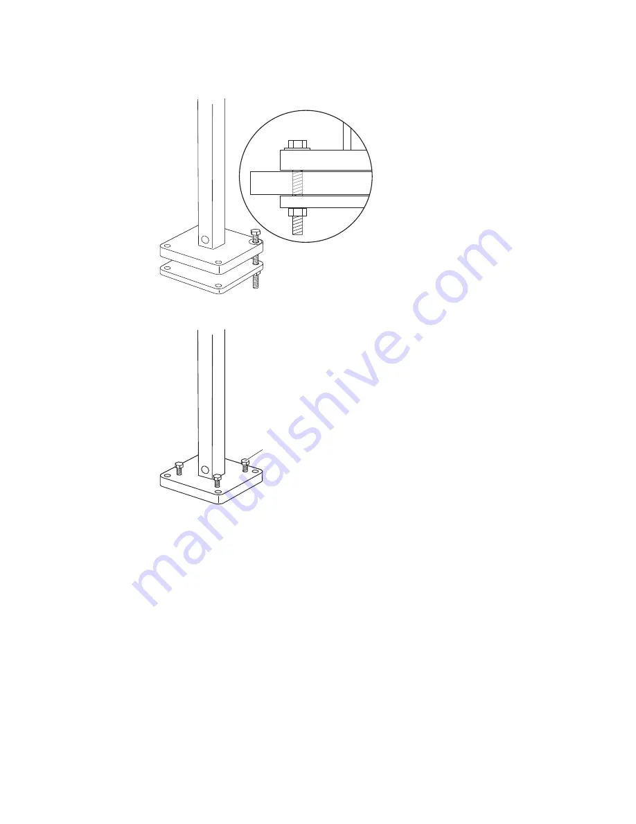
2.
P
lace washers on the stand base then the mounting bolts through the stand
base and mounting surface. Thread into the stand clamp placed under the
mounting surface.
3. Add the leveling screws if needed. Use in case the mounting surface is uneven.
The stand must be level
4. Pull the display cable (optional) out of the cable exit (side or bottom), leaving
enough for the cable to attach to the display (optional).
5. Slide the stand cover all the way down and click into place. Make sure cables
exit the side of the stand cover if using side exit.
6. Verify that the camera is level and at the correct angle. Adjust if necessary.
Leveling
screws (x4)
Содержание AUTOCUBE 8200
Страница 1: ...User Guide AutoCube 8200 User Guide ...
Страница 6: ...iv AutoCube 8200 User Guide ...
Страница 8: ...vi AutoCube 8200 User Guide ...
Страница 42: ...34 AutoCube 8200 User Guide ...
Страница 54: ...46 AutoCube 8200 User Guide Laser Output Angle Invisible laser radiation output ...
Страница 55: ......
Страница 56: ... Honeywell 9680 Old Bailes Road Fort Mill SC 29707 www honeywellaidc com AUTOC EN UG 01 Rev G 9 18 ...


