


4-40
MAN0448_Issue 13_01-2010
5704 Control System
005704-M-5001 A03249
CHAPTER 4 - INSTAllATION INSTRUCTIONS
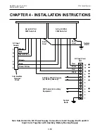
If the measuring resistance is in the negative supply line, a double
safety barrier must be used.
Note 1: *To ensure that the input circuit is properly referred to the safety
barrier it is necessary to connect the isolated 0V to the barrier
ground.
2: The above diagram shows the sensor connections for Channel
1. The connections for Channels 2, 3 and 4 are similar and
their pin connection numbers are shown below:
Channel
Sensor Connection
S
01
0V
Quad Relay
1
15
17
19
Interface Connections
2
16
18
20
3
21
23
25
4
22
24
26
IS lifeline Sensor With Double Safety Barrier
Содержание 5704
Страница 1: ...System 57 5704 Control System Operating Instructions ...
Страница 4: ...4 MAN0448_Issue 13_01 2010 5704 Control System 005704 M 5001 A03249 ...
Страница 6: ...6 MAN0448_Issue 13_01 2010 5704 Control System 005704 M 5001 A03249 User Notes ...
Страница 14: ...1 8 MAN0448_Issue 13_01 2010 5704 Control System 005704 M 5001 A03249 User Notes ...
Страница 41: ...2 27 MAN0448_Issue 13_01 2010 5704 Control System 005704 M 5001 A03249 Chapter 2 System Description User Notes ...
Страница 63: ...3 22 Chapter 3 Controls and Facilities MAN0448_Issue 13_2010 5704 Control System 005704 M 5001 A03249 ...
Страница 121: ...4 58 MAN0448_Issue 13_01 2010 5704 Control System 005704 M 5001 A03249 Chapter 4 Installation Instructions User Notes ...
Страница 183: ...8 14 MAN0448_Issue 13_01 2010 5704 Control System 005704 M 5001 A03249 Chapter 8 Specification User Notes ...
Страница 187: ...9 4 Chapter 9 Ordering Information MAN0448_Issue 12_01 2010 5704 Control System 005704 M 5001 A03249 ...


