background image


20 

switch.  An extension cord may be used to reach a suitable electrical outlet.  Ensure that the 
extension cord is UL/CSA certified and of an appropriate wire gauge for the application.   
 
Once plugged in, the touch screen display on the Control Valve (1) will illuminate.  The Control 
Valve (1) may need to reset its piston to the home position when it is powered up.  If it does, the 
motor will run for a few seconds.  This is normal. 
 
The Control Valve (1) has been pre-programmed for you, however, you will need to set the time of 
day and select the time of day that you prefer for the flush cycle to be done.  We normally 
recommend that the self-cleaning flush cycle be done in the middle of the night when it is unlikely 
that other water flows will be occurring.  The default time is 2:00 am.   
 
The touch screen is shipped with a protective plastic film on it that can be peeled off. 
 
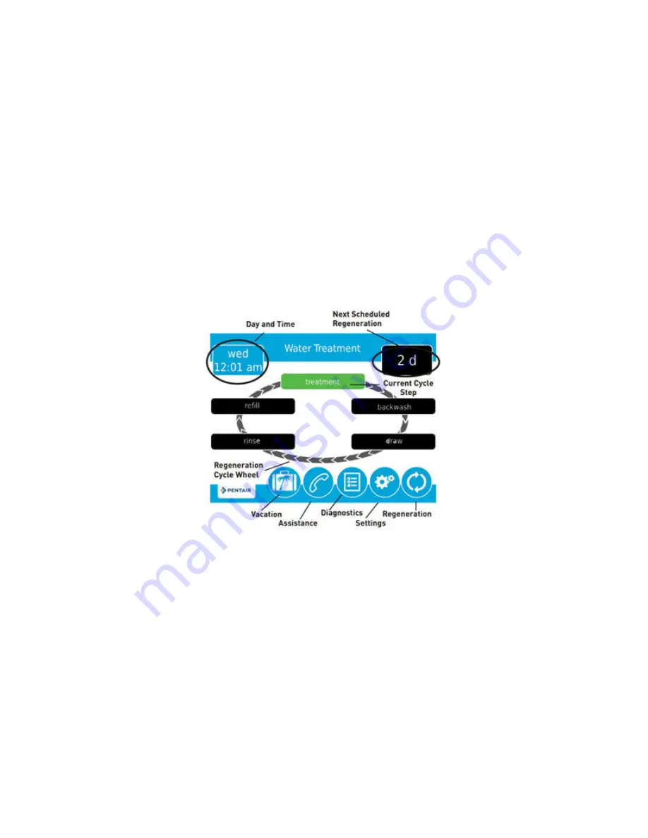
The following is the primary “Home Screen” or Main Menu: 


Items displayed in blue or grey can be touched to edit or obtain more information.  Items 
displayed in black are for information purposes only and cannot be selected. 
 
In the top left corner of the screen, you will find the current day of the week and time.   
 
In the top right corner, there is an indicator that will tell you when the next “regeneration” or flush 
cycle is scheduled to occur.   
 
In the middle if the screen is the regeneration cycle wheel which indicates the current valve cycle 
(indicated in green), and other applicable cycles (in black). 
 
The bottom menu bar provides the following options: 
 

Содержание UltraPlus+ UP-12

Страница 1: ...TH QUICK INSTALLATION KIT OWNER S MANUAL INSTALLATION GUIDE PLEASE READ THIS MANUAL CAREFULLY BEFORE ATTEMPTING INSTALLATION FAILURE TO FOLLOW THESE INSTRUCTIONS MAY VOID YOUR WARRANTY CAUSE INJURY OR RESULT IN PROPERTY DAMAGE ...

Страница 2: ...m is designed to offer low maintenance operation The control valve will perform regular maintenance functions automatically For your convenience your system has been pre programmed for you by our technicians Should you need to change any of the settings simply follow the instructions provided in this manual It is highly recommended that you consult your dealer before making any programming changes...

Страница 3: ...V disinfection and or chlorination be applied for enhanced protection A Pressure Decay Test PDT after installation is strongly recommended if microbiological reduction performance is desired SPECIFICATIONS For optimal filtration the continuous service flow rate range should not be exceeded Satisfactory filtration can generally be achieved up to the maximum peak flow rate as long as this level of f...

Страница 4: ...de of these operating conditions may adversely affect the performance of your system may void your warranty and can result in membrane clogging water leaks and or property damage Water should be pre treated as necessary to ensure the following conditions are met Sediment Pre Filtration 5 microns or less Chlorine 1 0 ppm mg l maximum for continuous flow up to 2 000 ppm for cleaning only Iron less t...

Страница 5: ...re not using one our Quick Installation Kits AND the WellMate WM 9 Back Flush Pressure Tank this is NOT the correct installation manual for your installation Contact your dealer to obtain the correct manual Back Flush Where a single system is used on its own a Back Flush Pressure Tank with a minimum capacity of about 30 gallons is required minimum drawdown of 10 gallons so that the system can auto...

Страница 6: ... of the time These kits are designed specifically for use with the Wellmate WM 9 Back Flush Pressure Tank Do not use the quick installation kits if you are using an alternative pressure tank or if you are installing multiple systems in parallel configuration If you are not using one our Quick Installation Kits AND WellMate WM 9 Back Flush Pressure Tank this is not the correct installation manual f...

Страница 7: ... MEMBRANE VESSEL 4 BOTTOM TANK ADAPTER 5 BACK FLUSH PRESSURE TANK WELLMATE WM 9 6 BACK FLUSH PRESSURE TANK RETENTION CLIP BLUE 7 BACK FLUSH SOLENOID VALVE 8 BACK FLUSH SOLENOID WIRING KIT 9 INLET ASSEMBLY ...

Страница 8: ...MBLY 11 DRAIN FLOW RESTRICTOR ASSEMBLY may be attached to control valve 12 UPPER DRAIN ASSEMBLY 13 PRESSURE TANK ASSEMBLY 14 OUTLET ASSEMBLY 15 FORWARD FLUSH TUBE 34 16 PRESSURE TANK TUBE 45 17 FORWARD FLUSH SOLENOID VALVE ...

Страница 9: ...the fitting by loosening the collet again and depressing the collar evenly while pulling outward on the tube Helpful Tip When the collet is loosened and the fitting is unlocked the fitting can be rotated as necessary to correctly align the parts and fittings to achieve a perfect installation Asco Quick Connect Solenoid Connections These fittings are used on the solenoid valves To connect a tube pi...

Страница 10: ... there will be enough space surrounding the unit to facilitate maintenance You will also need access to at least one standard non switched grounded 120 volt 60 Hz electrical outlet The Fleck 5810XTR2 control valve comes with a 10 foot long power cord The back flush solenoid valve and forward flush solenoid valve if so equipped require a standard electrical outlet for power as well An extension cor...

Страница 11: ...crewing them counterclockwise They can be recycled or kept for future use 2 Apply a very small amount very thin coat of food grade silicone lubricant to the large o ring on the underside of the Bottom Tank Adapter 4 Attach the Bottom Tank Adapter 4 to the bottom of the Membrane Vessel 3 by screwing it clockwise hand tight Excessive force is not required to achieve a good seal Do NOT use pipe dope ...

Страница 12: ...rection make sure that the riser tube inside the tank inserts into the center hole in the control valve as you screw down the valve Continue turning until you start to feel resistance Then grasp the base of the control valve and turn 1 4 to 1 2 turn further until snug The front of the control valve should face the UltraPlus graphics on the front of the Membrane Vessel 3 Do NOT use pipe dope or Tef...

Страница 13: ... optimal solenoid valve life and performance we recommend that it be arranged such that the inlet pipe extends to the right when facing the Control Valve 1 so the solenoid valve can be mounted horizontally 2 Connected the Back Flush Solenoid Valve 7 to the Inlet Assembly 9 using the Asco Quick Connect Fitting Note the directional flow arrow on the solenoid valve This is extremely important If inst...

Страница 14: ...be 15 to the John Guest Elbow at the bottom of the Lower Tank Assembly 10 on the assembled Membrane Vessel Hold the Lower Tank Assembly 10 in your hand when you push the tube in so that you do not apply pressure on the assembly that may break it 2 Connect the Forward Flush Solenoid Valve 17 to the Forward Flush Tube 15 using the Asco Quick Connect Fitting Confirm that the flow direction on the sol...

Страница 15: ...lush Pressure tank 3 if necessary such that the Pressure Tank Tube 16 is perfectly vertical and the tee on the Outlet Assembly 14 is directly above the elbow on the Pressure Tank Assembly 13 PLUMBING CONNECTIONS Check all John Guest fittings to make sure the collet has been tightened and the fitting has been secured Check all Asco solenoid valve fittings as well Turn off the household main water s...

Страница 16: ...loor joist to minimize noise transfer during the flush cycles Ensure that the drain line is secured along its route to the drain The drain line will be under pressure when the flush cycles are working therefore make sure the drain line is well secured so it cannot move around when pressurized If not adequately secured the drain line could vibrate during a flush cycle and cause excessive noise If t...

Страница 17: ...box if applicable to the wall behind your filter system Screws and anchors are provided in a plastic parts bag strapped to one of the cables These 2 control boxes are the same so don t worry which is which until you connect them to the solenoid valves and Control Valve only the actual solenoid valves are different ...

Страница 18: ... gland and nut These parts are shipped attached to the wire from the solenoid wiring kit control box 3 For each solenoid insert the wire upwards through the Control Valve 1 head base plate allowing the threaded end of the cable gland to insert through the hole Use the gland nut to secure the cable gland as shown below 4 Loosen the cable gland s so that you can extend the wire s forward to the bott...

Страница 19: ...he control box es to the solenoid valves Place the rubber gasket in parts bag between the solenoid valve coil green and the plug on the end of the wire from the control box Secure the connection with the screw provided START UP THE SYSTEM The Fleck 5810XTR2 Control Valve 1 comes with a 10 foot long electrical cord Plug the control valve power cord into the Control Valve 1 The electrical port on th...

Страница 20: ...done in the middle of the night when it is unlikely that other water flows will be occurring The default time is 2 00 am The touch screen is shipped with a protective plastic film on it that can be peeled off The following is the primary Home Screen or Main Menu Items displayed in blue or grey can be touched to edit or obtain more information Items displayed in black are for information purposes o...

Страница 21: ...mode if no user input has been made for 5 minutes To turn the screen back on just touch it TURN ON THE WATER Ensure that the bypass is in the bypass position by turning the 2 blue handles on the Bypass Assembly 2 so they are perpendicular to the direction of water flow Turn on the main water supply Open a cold water tap nearby and let the water run for a few minutes until the system is free of for...

Страница 22: ... for 1 minute at 2 GPM If you do have the Forward Flush Kit Step 1 Backwash Back Flush factory pre set for 5 minutes at 2 GPM Step 2 Rinse Forward Flush factory pre set for 1 minute at service flow rate Unless directed by a water treatment professional familiar with this system we do not generally recommend that you alter of any of the system programming During each step of flush cycle the digital...

Страница 23: ...the hour minutes and pm am in the same manner When you are satisfied that all of the settings are correct press the checkmark icon in the bottom right corner of the screen To cancel your changes and return to the home screen press the X icon at any time CHANGING BASIC SETTINGS The Settings Mode allows you to set the frequency of the back flush and the time of day that the flush cycles will take pl...

Страница 24: ...nlikely that water will be used for other purposes To adjust the time of day that the flush cycles will occur touch regen time and two blue arrows will appear Touch the arrow on the left to adjust to an earlier time and the arrow on the right to adjust to a later time When you are satisfied that all of the settings are correct press the checkmark icon in the bottom right corner of the screen To ca...

Страница 25: ... totalizer meter was last reset To reset the peak flow meter touch totalizer and then select the icon in the bottom right corner of the next screen The totalizer meter will be reset to zero The second screen displays when the last regeneration flush cycle occurred as well as the software version that is used by your control valve The third screen indicates the number of flush cycles that the valve...

Страница 26: ...nits gpG VALVE Parameter Setting system 4 valve 5810 regen type filter mtr delayed day override time driven 1 regen time 2 00 am vol override volumetric 1000 G REGEN Parameter Setting regen flow filter step 1 backwash time 1 5 m step 2 rapid rinse time 2 1 m RELAY Parameter Setting auxiliary 1 cycle based auxiliary 2 cycle based Aux 1 Cycle Based treatment off rapid rinse off backwash on draw na t...

Страница 27: ...ower is restored the control will resume the cycle from the point where power failed Note that if power fails during a flush cycle the valve will remain in its current position until power is restored The drain line plumbing configuration should include all required safety components to prevent overflows resulting from a power failure during backwash The control will not start a new flush cycle wi...

Страница 28: ...fects in material and workmanship for the following periods from the date of purchase provided that your system was purchased from an Authorized dealer operated in accordance with operating conditions stated herein and provided that it was installed in accordance with these instructions Membrane Vessel 3 Years Pro Rated Control Valve 5 years Back Flush Pressure Tank Wellmate WM 9 5 years residenti...

Страница 29: ...rt or otherwise shall not exceed the actual purchase price paid by the authorized distributor or consumer for the product In no event shall HomePlus Products Inc be liable to the distributor or any other person or entity for special incidental consequential or punitive damages including but not limited to property loss loss of incomes or loss of use damages arising out of the manufacture sale or s...

Отзывы: