HT1635A/B Wearable Sports Bracelet LED Display Application
4 / 19
AN0393E
After system power is applied, the HT1635A/HT1635B devices will be initialised by an
internal power-on reset circuit. The status of the internal circuits after initialisation is as
follows.
•
System oscillator will be off
•
COM0~COM7 outputs are high impedance
•
ROW outputs will all be low
•
The LED display will be in an off state
•
ROW outputs are set to 16/16 PWM duty
•
The blinking function will be in an off state
It should be noted that data transfers on the 4-wire/I
2
C bus should be avoided for more
than 1ms following a power-on reset to the devices to allow the reset initialisation
operation to complete.
Dimming Circuit
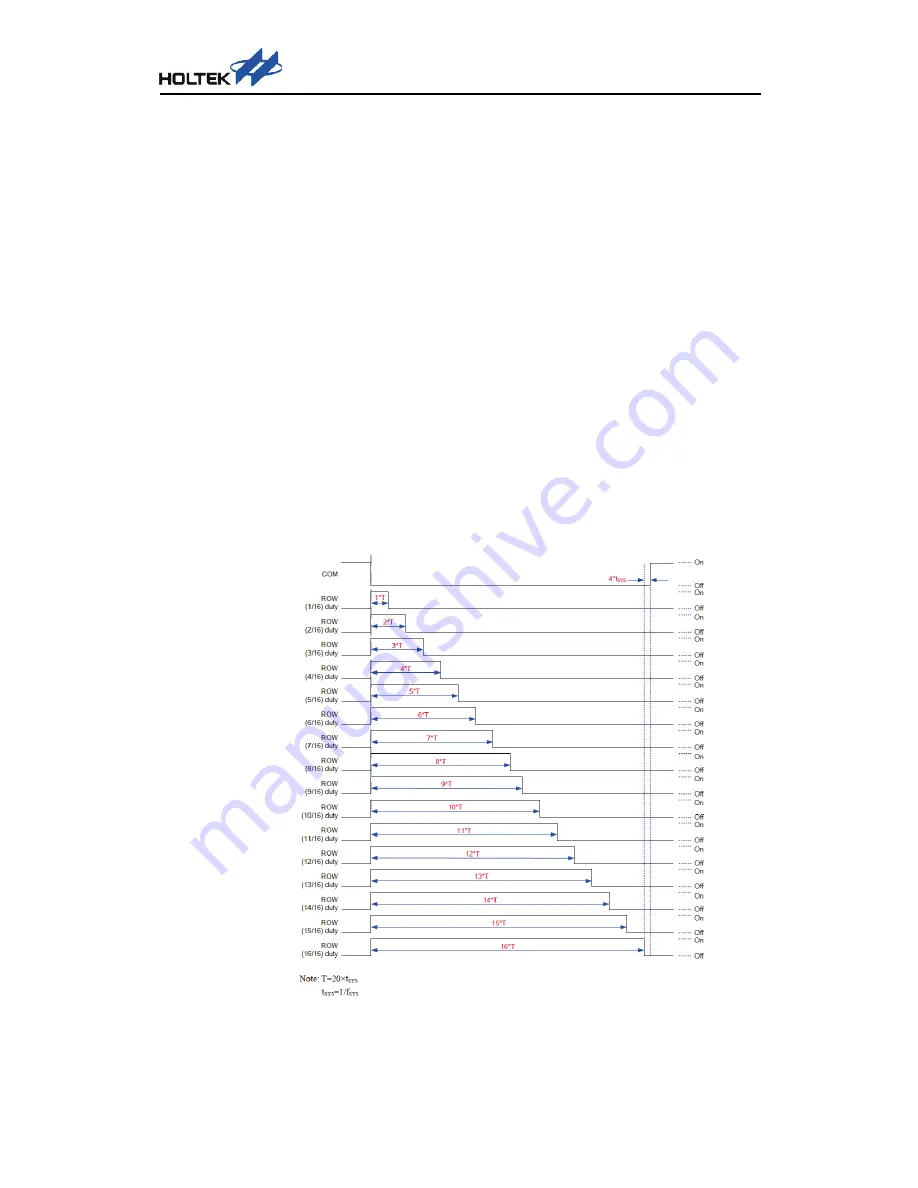
The HT1635A/HT1635B devices have an integrated 16-level PWM dimming circuit. The
dimming circuit uses the command received by the interface to set up the related
dimming register. In this way, all of the ROW outputs duty can be adjusted to implement
the brightness control of the entire display screen. The ROW dimming timing is shown in
the following figure.


