


HT1635A/B Wearable Sports Bracelet LED Display Application
14 / 19
AN0393E
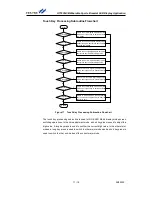
When the demo board is powered-on, the HT66F50 will implement a system initialisation,
provide a 100ms delay to ensure that the HT1635A/HT1635B internal power-on reset
circuit has enough time to complete the reset operation and then communicate with the
HT1635A/HT1635B for initial setup. In the main program loop, the host MCU firstly
detects the power supply method and then executes a key scanning, system clock update
and display update.
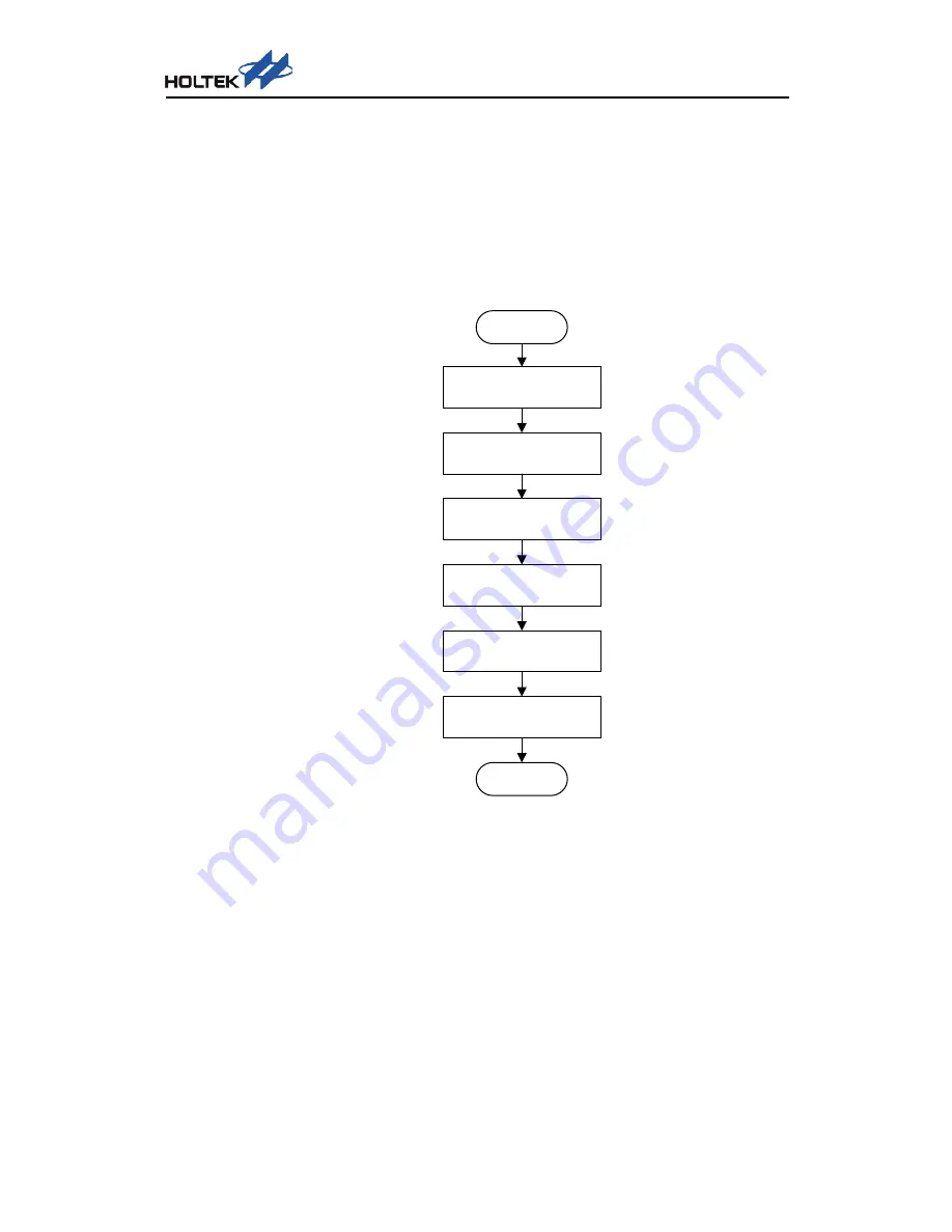
HT1635A/HT1635B Initialisation Flowchart
Start
COM Driving Type Setup:
PMOS
Blinking Frequency Setup:
Blinking Off
PWM Duty Setup:
16/16 PWM Duty
Operating Mode Setup:
RC Master Mode0
SYS Setup:
SYS EN
LED Setup:
LED ON
Return
Figure 14 HT1635A Initialisation Flowchart (4-wire Interface)