background image

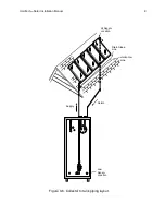
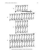
Figure 3.8 shows piping routines for different numbers of collectors placed on a sloped 
roof.  Because excessive expansion and contraction of the headers with temperature 
swings can cause failure in the piping, it is recommended that no more than five four 
foot wide collectors be joined together in one bank as shown in fig. 3.8(a).  However, six 
collectors may work if care is taken to assure there are no binding points in the piping.  
Symmetry is important in collector arrays to help balance the flow through each 
collector.

The collectors must have the recommended drain slope toward the supply (inlet) line to 
drain properly.  In addition, the return line must be on the opposite top corner from the 
supply line to insure uniform flow through all collectors.  The diagrams in fig. 3.8 show 
that the path lengths for every fluid circuit are the same, eliminating the need for 
balancing valves.

Figure 3.8(b) shows two banks of five collectors mounted in a single row on a common 
sloped line.  This arrangement is called a "row tilt".  A spacing of 5-6 inches between 
banks of collectors allows enough space to bring an insulated supply header between 
the collectors.

Figure 3.8(c) shows two rows of collectors arranged vertically over each other.  Notice 
the return header connections.  The water from the lower row must rise and join the 
higher row to guarantee all collectors are full before any water can return to the tank.

Figure 3.8(d) shows collectors arranged vertically and horizontally.  It is a combination of 
two (b) type circuits placed one over the other.  The same result can be achieved with 
two (c) type circuits placed side by side.  The choice depends upon whether there is 
more horizontal or vertical room for the supply headers. 

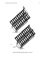
Large arrays may have several rows of collectors on a flat roof.  Figure 3.9 shows two 
banks of collectors piped as a single array and as separate arrays.  In fig. 3.9(a) the 
banks are joined by a common return line which is elevated from the first bank to the 
second bank.  This line must have continuous upward slope to the high point shown in 
the figure to insure that all collectors in both banks fill completely before any of them 
can drain.  This piping scheme preserves the filling requirements and eliminates the 
need for balancing valves.  However, the long runs between rows require mechanical 
supports to prevent traps and to properly support the piping.

A more common arrangement is shown in fig. 3.9(b).  In this case, there are separate 
return lines from each row that join below the collectors in a common return line.  
Individual balancing valves are required in the supply lines to set the flow rate in each 
row.  The return lines can be joined as desired, but must maintain a proper drain slope 
to the tank.

All pipe runs must slope continuously from the collectors to the tank.  The minimum 
slope is 1 inch in 20 feet, but should be as much as possible.  There must be no traps  
in the line.  

HoloTech

tm

 Solar Installation Manual 

11

Содержание HotoTech

Страница 1: ...HoloTechtm Solar Hot Water System Installation Manual Ben Gravely PhD Holocene Technologies 1241 Wicker Drive Raleigh NC 27604 c 2012...

Страница 2: ...Frame and Collector Mounting 3 2 Collector Piping 3 3 Pipe Insulation 3 4 Solar Controls and Wiring 3 5 Collector System Startup 4 Domestic Hot Water 4 1 Piping 4 2 Re circulator DHW Controls 4 3 DHW...

Страница 3: ...th the less solar energy will be collected The placement of the collectors and the tank should be determined including the routing for piping between the components Shading considerations can be inclu...

Страница 4: ...ig 2 1 for examples The tank must be installed on a floor or surface substantial enough to carry the full weight of the tank plus water Table 2 1 shows approximate filled weights of five common reside...

Страница 5: ...the wiring finished the system startup procedure can begin Make sure the pressurized domestic hot water line and standard water heater are purged and filled with water Fill the tank using the boiler...

Страница 6: ...rray of solar collectors The first is the south facing direction south azimuth and the second is the tilt of the collectors up from the ground both described in section 1 The third angle is critical t...

Страница 7: ...ting from the lowest corner of the collector array On the opposite end mark the distance up the roof as shown in fig 3 3 Another method is to hold a bubble level perpendicular to the level line and 1...

Страница 8: ...and under the feet with silicone sealant to keep water out Make sure to point the narrow dimension of the feet up and down the roof to prevent damming rain water and trapping leaves and debris The co...

Страница 9: ...loTechtm Solar Installation Manual 9 Hi Sensor Location Horizontal Line Drain Slope Line Supply Return Low Sensor Location Figure 3 2 Collector Piping Circuit Figure 3 6 Collector to tank piping layou...

Страница 10: ...rray from the lowest corner 2 water exits the collector array from the highest corner 3 the water from all collectors must rise to a common high point before it is allowed to drain back to the tank 4...

Страница 11: ...e any water can return to the tank Figure 3 8 d shows collectors arranged vertically and horizontally It is a combination of two b type circuits placed one over the other The same result can be achiev...

Страница 12: ...HoloTechtm Solar Installation Manual 12 b c Figure 3 3 Collector Piping Diagrams a Drain Slope d Figure 3 8 Collector piping for arrays in the same plane...

Страница 13: ...HoloTechtm Solar Installation Manual 13 Supply Return Supply Return Figure 3 4 Dual Bank Piping Diagrams a b Flow Setter Valves Figure 3 9 Collector piping for arrays on a flat roof...

Страница 14: ...rigid foam products Use the next thickness up Insulate all piping between the collectors Apply silicone sealant between the pipe jacket and the collector box to keep water from getting in and wetting...

Страница 15: ...s lower temperature water to the heat source The low temperature sensor position is the bottom of the solar tank for collector circuits or the return line of the pool for the pool spa circuits The ter...

Страница 16: ...ver the flat part of the sensor not the round part to avoid crushing the body of the sensor Connect the hook up wire to the sensor leads Use wire nuts or crimp connectors and fill with silicone sealan...

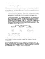
Страница 17: ...ch to the AUTO position Refer to Table 3 3 Connect a low value resistor low R hot across the COL terminals and observe the controller response The system should turn on since the COL terminals appear...

Страница 18: ...dard water heater a supply cold line from the bottom of the water heater and a return hot line to the top of the water heater Figure 4 2 illustrates the piping diagram The dip tube in the water heater...

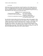
Страница 19: ...rasp the two pipes going in and out of the DHW exchanger Note the flow of water through the exchanger by the change in temperature of the pipes as the water flows through them Recirculator Startup Tur...

Страница 20: ...quickly The different electrical circuits of a HoloTechtm solar system are all independent and can be treated separately This simplifies the procedure considerably The circuits are Collectors Domestic...

Страница 21: ...sensor 3k and the third simulates the very hot OVT condition 1k Set the controller switch to AUTO and connect the STO COL and OVT resistors to the terminals in the patterns indicated in Table A1 1 No...

Страница 22: ...ure vs Resistance HoloTechtm solar controls use 10K thermistor temperature sensors These devices change resistance with temperature They are defined by having 10K resistance at 25 C 77 F HoloTechtm So...

Страница 23: ...uns pumps water flow stops Height greater than pump head Air locked lines traps in lines If a pump does not pump water the first test should be to swap out the capacitor If this does not work remove t...

Страница 24: ...equirements solar performance and economic benefit that were recognized as authorized analytical methods by HUD the NC Energy Division and the US Army Corp of Engineers He has presented numerous paper...

Отзывы: