3.2
Collector Piping
The recommended flow rate for each collector is 0.025+/-.005 GPM/ft2. Consult the
chart below to determine the proper pipe size for different collector areas. Use only
metal pipe in the collector loop. Either type L or M copper is satisfactory, since the
piping is operated only at atmospheric pressure. The supply and return pipes are the
same size.
Table 3.2 Collector Circuit Pipe Sizing
Area of Collectors
Pipe Diameter
20-60 ft2
1/2 (3/4 in. recommended)
80-240 ft2
3/4 in.
240-400 ft2
1 in.
For collector piping runs longer than 50 feet one way, use the next pipe size. For roof
penetrations in residential type construction, use neoprene roof flashing boots made for
vent pipes. The hole diameter should be the outside diameter of the pipe insulation,
usually 2-1/2 - 3 inches.
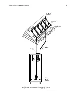
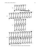
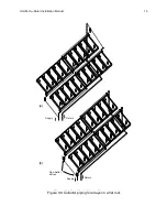
The piping arrangement for the collector array must follow these rules
1. water enters the collector array from the lowest corner.
2. water exits the collector array from the highest corner.
3. the water from all collectors must rise to a common high point before
it is allowed to drain back to the tank.
4. there can be no traps in the lines from the collectors to the tank.
The rules assure that all the collectors will fill
completely before any one drains, and all the
water from the collectors can drain completely
to the tank. 95/5 solder is recommenced for all
joints on the collectors.
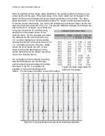
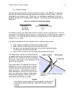
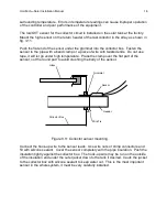
A good technique for soldering the collector
manifolds is to use a solder shield, or flame
shield, to protect the grommet from excess
heat. See fig. 3.7. The shield is a piece of
sheet metal with a slot cut out to go over the
pipe. Top and bottom collector headers are
joined directly together to form a common
manifold for all collectors in a bank.
HoloTech
tm
Solar Installation Manual
10
1" coupling
solder shield
95/5 solder
Figure 3.7 Solder shield for joining
collectors.
NOTE
The collector header pipes must be completely cleaned of all
black plating before soldering! Solder will not stick to black
plating!


