background image

HMPRO50 OPERATOR’S MANUAL

www.holemaker.com

5

GROUNDING INSTRUCTIONS 

POWER SUPPLY REQUIREMENTS

WARNING! 

Improperly connecting the grounding wire can result in the risk of electrical shock. 

Prior to use check condition of the power cord, which has to be free of any cuts,  or similar damages. 

Attention!:  This unit has a class one of insulation and
                     absolutely requires the power source
                     to be equipped with a protection circuit. 

Power source should be protected with the difference-current circuit cut-out and protected with a 10A fuse - for 230V. 
At building sites, power should be supplied from a separation transformer such as Type AVM, with minimum power of 
2000 VA and with second class protection.

Check with a qualified electrician if you are in doubt as to whether the outlet 
is properly grounded. Do not modify the plug provided with tool. Never remove 
the grounding prong from the plug. If the cord or plug is damaged, have it 
repaired before using. If the plug will not fit the outlet, have a proper outlet 
installed by a qualified electrician. The Holemaker must be plugged into an 
appropriate outlet, properly installed and grounded in accordance with all codes 
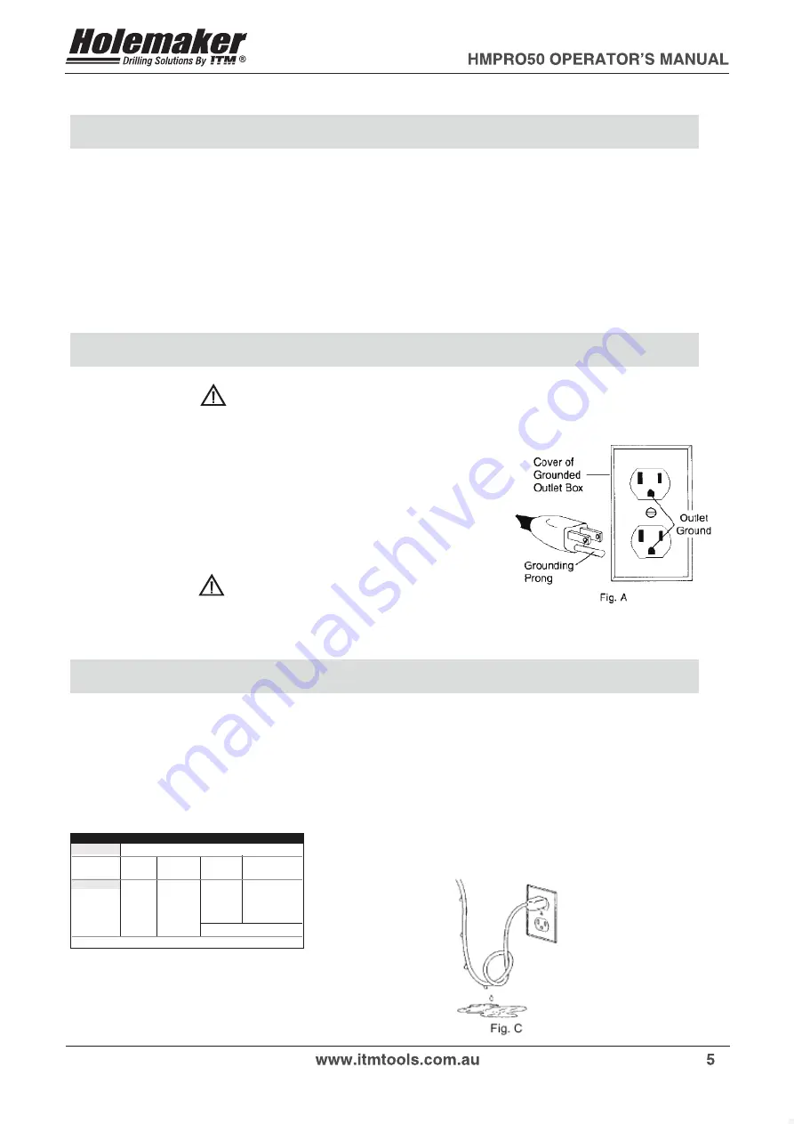
and ordinances. The plug and outlet should look similar to those in Figure A.
If in doubt of proper grounding, call a qualified electrician. 

WARNING! 

DO NOT USE HOLEMAKER DRILLING MACHINES ON SURFACES OR MATERIALS BEING 
WELDED

.

DOING  SO  CAN  RESULT  IN DAMAGE TO THE DRILLING MACHINE. 

EXTENSION CORDS 

Use only 3-wire extension cords that have 3-prong grounding-type plugs and 3-pole receptacles that accept the 
tool’s plug. Replace or repair damaged cords. Make sure your extension cord is in good condition. When using 
an extension cord, be sure to use one heavy enough to carry the current your product will draw. An undersized cord 
will cause a drop in line voltage resulting in loss of power and overheating. See table for the correct size to use 
depending on cord length and nameplate amperage rating. If in doubt, use the next heavier gauge. The smaller the 
gauge number, the heavier the cord. 

12-16

VOL TS 

240V

AMPERAGE

0-6
6-10
10-12

14

RECOMMENDED  WIRE GAUGE 

12

MINIMUM  GAUGE  FOR EXTENSION  CORDS 

TOTAL LENGTH  OF  CORD  IN  METRES 

0 - 15 

15 - 30 

30 - 60 

60 - 90 

18 16 16 14 
18 16 14 12 
16 16 14 12 

NOT RECOMMENDED 

DRIP LOOP: To help prevent cutting fluids from traveling 
along power cord and contacting power source, tie a drip 
loop in power cord as shown in Figure C. 

5

Содержание HMPRO50

Страница 1: ...UTTING AREA OR MACHINE ARBOR HEARING PROTECTION REQUIRED EYE PROTECTION REQUIRED Ver 1 10 14 08 2015 Holemaker Portable Magnetic Drilling Machine OPERATOR S MANUAL WARNING BEFORE USE ENSURE EVERYONE USING THIS MACHINE READS AND UNDERSTANDS ALL SAFETY AND OPERATING INSTRUCTIONS IN THIS MANUAL e s a h c r u P f o e t a D l a i r e S HOLEMAKER PRO 50 BEWARE OF ROTATING MACHINE PARTS LINE VOLTAGE PRES...

Страница 2: ...21 LIMITED WARRANTY Industrial Tool Machinery Sales hereinafter refered to as ITMS will within twelve 12 months from the original date of purchase repair or replace any goods found to be defective in materials or workmanship This warranty is void if the item has been damaged by accident neglect improper service or other causes not arising out of defects in materials or workmanship This warranty do...

Страница 3: ... When not in use tools should be stored in a dry high and locked up place out of reach of children 6 Do Not Force Tool It will do the job better and safer at the rate for which it was intended 7 Use Right Tool Do not force a small tool or attachment to do the job of a heavy duty tool Do not use tool for unintended purpose For example Do not use a circular saw for cutting tree limbs or logs 8 Dress...

Страница 4: ...ure switches are off before connecting to a power source 16 Outdoor Use Of Extension Cords When tool is used outdoors use only extension cords intended for use outdoors and so marked 17 Stay Alert Watch Fig 1 Always use cutter guard supplied with machine to reduce the risk of injury refer fig 1 what you are doing Use common sense Do not operate tool when you are tired Do not use when taking medica...

Страница 5: ...y installed and grounded in accordance with all codes and ordinances The plug and outlet should look similar to those in Figure A If in doubt of proper grounding call a qualified electrician WARNING DO NOT USE HOLEMAKER DRILLING MACHINES ON SURFACES OR MATERIALS BEING WELDED DOING SO CAN RESULT IN DAMAGE TO THE DRILLING MACHINE EXTENSION CORDS Use only 3 wire extension cords that have 3 prong grou...

Страница 6: ...m Gear 2 400rpm Insulation class First Arbor bore MT 2 Tool holder 3 4 Weldon 19 05 mm Capacities max Holemaker cutter diameter 52mm max drilling depth with standard arbor 52mm max drilling depth with optional arbor 75mm Magnet Dead Lift on 25 mm plate 12000 N Dimensions electromagnetic base 90x180x48 mm Length of the power cord 3 m Total weight 16 5 kg Noise level 85 dB ...

Страница 7: ...e up in the spindle Turn the arbor until it bottoms out in the spindle and then tap lightly with a plastic hammer to secure SPECIAL INSTRUCTIONS 1 Read and follow operator s manual thoroughly 2 DO NOT touch rotating cutter or parts 3 Always stop machine completely and unplug from power source before changing cutters clearing swarf refilling lubrication or performing adjustments 4 Never wear loose ...

Страница 8: ...ts the slug which is a by product of drilling the hole with a centre free cutter START UP AND OPERATION The machine is supplied in a metal box Some components of the drilling machine are coated with grease film for protection during transit and storage Prior to use of the machine this should be wiped clean NOTE As a power saving function Switching the Magnet Switch 1 to I will supply the electroma...

Страница 9: ...el under the magnet is flat wipe brush or sand down clean surface where you intended to place the drilling machine so that you remove rust paint dirt etc which would reduce adhesive power of the electromagnetic base Install annular cutter in the machine before plugging it into mains Place the machine so that the tool is over the centre of the hole you intend to make and turn the magnetic base ON A...

Страница 10: ...ling liquid to fill the whole system Turn the motor on Bring the cutter gently into contact with the work piece and slowly start to apply pressure on the cutter Making a hole with an annular cutter should ideally be done in one pass Do not peck drill WARNING When the annular cutter goes through the material the slug can be pushed out often with considerable strength Pay attention to avoid injury A...

Страница 11: ...ll body visible through the openings in the slider 5 To loosen screws 2 the slider should be placed in such a position using feed handles so that the openings make the screws visible After loosening the screws slide the slider up and down several times so that the pressure strip aligns itself and cancels clearance After carrying out these steps and canceling clearance tighten screws 2 starting fro...

Страница 12: ...hine must be in a upright position to operate properly Dirt or debris in coolant tank Consistency of coolant mixture too thick Is correct pilot pin being used Vent hole in coolant tank lid blocked 5 Slugs not ejecting from cutter Lack of coolant causing slugs to expand in cutter bore Is correct pilot pin being used Possible broken internal arbor parts 6 Breaking cutters How is coolant being applie...

Страница 13: ...0V CONTROL PANEL 230V GUARD ASSY STOP ROD LOWER SLEEVE UPPER SLEEVE SAFTY PIPE PINION SHAFT SPOKE HANDLE INCLUDING KNOB ASSY ARBOR SET AMT2 C19 2 2 COOLANT SYSTEM POWER CORD 230V 3x1 5 STRAIN RIELIEF PG11 NYLON WASHER SR1940 EXTERNALE RETAINING RING 28z SCREW M4X10 PHCRMS SPRING WASHER 4 1 SPRING WASHER 4 3 PUSH SPRING SOCKET BUTTON HEAD CAP SCREW WITH FLANGE M5x25 SOCKET BUTTON HEAD CAP SCREW WIT...

Страница 14: ...SPPRO5001 FRAME ASSEMBLY ITEM PART NUMBER QTY N O I T P I R C S E D SPPRO500101 SPPRO500102 SPPRO500103 SPPRO500104 SPPRO500105 MAIN BODY ASSY D RING STRAP ELECTROMAGNETIC BASE SPRING WASHER 6 1 HEX SOCKET BOLT M6x25 1 1 1 2 1 3 1 4 1 5 1 1 1 4 4 14 ...

Страница 15: ... SPPRO50010104 SPPRO50010105 SPPRO50010106 SPPRO50010107 SPPRO50010108 SPPRO50010109 SPPRO50010110 MAIN BODY PRESSURE PLATE SLIDE INSERT LEFT SELF LUBRICATING SLEEVE 28 05H7x32x16 SPRING WASHER DISC SPRING 4 2x10x0 5 HEX SOCKET BOLT M5X20 ROUND WASHER 5 3 HEX SET SCREW M5X10 NUT M5 1 1 1 1 1 2 1 1 3 1 1 4 1 1 5 1 1 6 1 1 7 1 1 8 1 1 9 1 1 10 1 1 1 2 4 32 5 5 3 3 ...

Страница 16: ...E ASSY NEUTRAL MOTOR WIRE ASSY SHIFT DRIVE PIN USA 5 COMPRESSION SPRING USA 5 SHIFT LEVER SHIFT PIN SHORT GEAR z 52 m 1 25mm SQUARE KEY 6x6x15 WASHER THRUST 10x1 2x2 BEARING WASHER 8 1 SHIFT FORK PINION SHAFT z12 z20 ASSY PINION SHAFT Z 12 ASSY LABEL SHIFT LEVER BEARING NEEDLE RHNA 081210 SPRING PIN 4x16 EXTERNALE RETAINING RING 25z SPRING WASHER M5 HEX SOCKET BOLT M5x35 HEX SOCKET BOLT M5x40 SCRE...

Страница 17: ...PRO50020105 SPPRO50020106 SPPRO50020107 SPPRO50020108 SPPRO50020109 SPPRO50020110 SPPRO50020111 MOTOR COVER GUIDE FAN ARMATURE ASSY 230V ARMATURE TOOTH END z12 FIELD 230V UPPER HOUSING CROSS RECESSED PAN HEAD TAPPING SCREW 4x16 SPRING WASHER BRUSH 230V SPRING BRUSH HEXAGON BOLT M4x73 2 1 1 2 1 2 2 1 3 2 1 4 2 1 5 2 1 6 2 1 7 2 1 8 2 1 9 2 1 10 2 1 11 1 1 1 1 1 1 4 1 2 2 2 17 ...

Страница 18: ...020211 SPPRO50020213 SPPRO50020214 SPPRO50020215 GEARCASE SPINDLE GEAR RACK UPPER SPINDLE BEARING 6206 2Z P6 S 30x62x16 UPPER SPINDLE BEARING 6005 25x47x12 BEARING NEEDLE RHNA 101610 BEARING NEEDLE RHNA 081210 EXTERNAL RETAINING RING 30z EXTERNALE RETAINING RING 25z INTERNAL RETAINING RING 62W PIN 6x14 SPRING WASHER 5 1 HEX SOCKET BOLT M5X20 2 2 1 2 2 2 2 2 3 2 2 4 2 2 5 2 2 6 2 2 7 2 2 8 2 2 9 2 ...

Страница 19: ... SPPRO50021701 SPPRO50021702 SPPRO50021703 SPPRO50021704 GEARSHAFT 12T 20T 2x2 HELICAL INPUT GEAR z46 WOODRUFF KEY 3x3 7 BEARING BALL 8X22X7 1 1 1 1 QTY SPPRO500218 PINION SHAFT Z 12 ASSY ITEM PART NUMBER DESCRIPTION 2 18 1 2 18 2 2 18 3 SPPRO50021801 SPPRO50021802 SPPRO50021803 GEARSHAFT 12T 2x2 CLUSTER GEAR z52 z44 m 1mm SQUARE KEY 3x3x36 1 1 1 19 ...

Страница 20: ...ANEL ASSEMBLY ITEM PART NUMBER DESCRIPTION 3 1 3 2 3 3 3 4 3 5 3 6 SPPRO500301 SPPRO500302 SPPRO500303 SPPRO500304 SPPRO500305 SPPRO500306 PANEL PLATE ASSY ELECTRONIC CONTROLLER SW 30M SWITCH START STOP 230V SWITCH MAGNET METAL LOCK INTERFERENCE ELIMINATOR 1 1 1 1 4 1 20 ...

Страница 21: ...HMPRO50 OPERATOR S MANUAL www holemaker com 21 21 ...

Страница 22: ......

Отзывы: